TOWER TRAINER 40 MKII ™ ALMOST-READY-TO-FLY RADIO CONTROLLED MODEL AIRPLANE ASSEMBLY INSTRUCTIONS F R A Wingspan: 62 in [1,550mm] Wing Area: 698 sq in [45.0 sq dm] Weight: 5 lbs [2,268 g] Length: 50.5 in [1,283mm] Wing Loading: 17 oz/sq ft [52 g/sq dm] Engine: .40 - .46 cu in [6.6 – 7.5cc] two-stroke Radio: 4 channel WARRANTY Tower Hobbies guarantees this kit to be free from defects in both material and workmanship at the date of purchase.
TABLE OF CONTENTS INTRODUCTION INTRODUCTION..............................................................2 Thank you for purchasing our Tower Trainer 40 MKII ARF. This model has been specially created for you and other first-time radio control modelers. The Tower Hobbies Tower Trainer 40 MKII ARF offers nearly all the excitement of piloting a real airplane…and develops skills that will take you anywhere you want in your new hobby. ADDITIONAL ITEMS REQUIRED ...................................
ADHESIVES AND ASSEMBLING SUPPLIES If you have not flown this type of model before, we recommend that you get the assistance of an experienced pilot in your R/C club for your first flights. If you’re not a member of a club, your local hobby shop has information about clubs in your area whose membership includes experienced pilots. In addition to common household tools and hobby tools, this is the “short list” of the most important items required to assemble the Tower Trainer 40 MKII ARF.
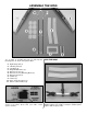
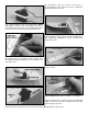
ASSEMBLE THE WING ❍ 1. In order to assemble the wing you will need the following items as shown in the photo above. #1 #2 #3 #4 #5 #6 #7 #8 #9 #10 #11 JOIN THE WING Right Wing Panel (1) Left Wing Panel (1) CA Hinges (8) Wing Dihedral Braces (2) Aileron Servo Tray (1) Aileron Servo Tray Mounting Blocks (2) Aileron Pushrods (2) Faslinks (2) Clevises (2) Nylon Torque Rod Horns (2) Silicone Clevis Retainers (2) ❍ 2.
the wing panels. Trim the root rib if necessary to accommodate the servo and the servo wire. Prepare the left wing panel the same way. ❍ 4. Test fit the aileron servo in the 3mm plywood aileron servo tray. If necessary, trim the opening in the tray to accommodate the servo. Once you are satisfied with the fit of the servo, remove it from the tray and set it aside for now. ❍ 7. Trim the covering from the ends of the root ribs on both wing panels.
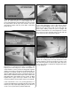
❍ 10. Test fit the wing joiner into one wing panel, then the other. Be certain the joiner is installed upright with the joiner angled upward for wing dihedral. Also make sure that the joiner slides in all the way to the centerline. Test fit the wing panels together with the joiner. Make certain both panels fit well. ❍ 12. Once satisfied with the fit of the joiner and the wing has the proper dihedral, it is time to glue the two panels together.
HOOK UP THE AILERONS Do the left wing first so the assembly matches the photographs the first time through. You can do one wing at a time, or work on them together. ❍ ❍ 4. Coat the “arm” portion of the aileron torque rod that slips inside the aileron and the groove and the hole in the aileron where the torque rod fits with 30-minute epoxy. Tip: You may want to use a toothpick to get epoxy into the hole drilled in the aileron for the aileron torque rod. ❍ ❍ 1. Take a close look at the supplied hinges.
❍ 9. Assemble the servo using the four servo grommets and four brass eyelets as shown in the sketch above. Insert the servo into the mount and mark the location for the 4 screws. Remove the servo and drill 1/16” [1.6mm] holes through the servo mount for the servo mounting screws. ❍ 7. Glue the two 8mm square x 38mm aileron servo tray mounting blocks that you cut to shape earlier to the aileron servo tray. Be sure that you glue the flat side of the blocks to the aileron servo mounting tray.
❍ 12. Assemble the two aileron pushrods made from two 200mm wire pushrods, clevises, and silicone retainers. To make the pushrods, thread the clevises onto the wire pushrods approximately 25 full turns. ❍ Cut the wire that extends beyond the Faslink; be certain to leave 1/16” [1.6mm] of wire protruding from the Faslink as shown in the photograph. ❍ 15. Install the remaining pushrod in the same manner. The above photo shows how your assembly should look when finished. ❍ 13.
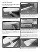
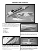
ASSEMBLE THE FUSELAGE MOUNT THE STABILIZER AND FIN ❍ 1. In order to complete this section you will need the following items as shown in the photograph above. You will also need the wing (not shown) for alignment purposes. #1 #2 #3 #4 #5 #6 Fuselage (1) Stabilizer (Stab) (1) Elevator (1) Fin (1) Rudder (1) CA Hinges (7) ❍ 3. Use a hobby knife with a sharp #11 blade and cut the covering from the openings on both sides of the fuselage for the stab.
❍ 5. Support the model with a small stand or cardboard box. Place the wing into the wing saddle on the top of the fuselage. Stand five to ten feet behind the model and view the stab and wing. If the stab and wing align with each other, proceed to the next step. If the stab and wing do not align, place a small weight on the “high” side of the stab to bring it into alignment.
11. Apply 30-minute epoxy to all joining surfaces of the stab. Slide the stab into position. Wipe away residual epoxy with a tissue dampened with rubbing/denatured alcohol. If the stab required a weight on one side or the other to align it with the wing, position the weight. Use the pin and string to confirm stab alignment. Do not disturb the model until the epoxy has fully hardened. ❍ 9. Remove the stab from the fuselage.
INSTALL THE WING MOUNTING DOWELS ❍ 1. For this step you will need the following items as shown in the photograph above. #1 #2 #3 #4 Fuselage (1) Wing Mounting Dowels (2) 2.6mm x 8mm Wood Screws (4) Molded Wing Dowel Covers (4) ❍ 3. Note: One of the wing mounting dowels is 3mm longer. Place the longer one in the position to the front of the fuselage. Insert both wing mounting dowels so they protrude an equal amount on both sides of the fuselage. Mix ¼ oz. [7ml] of 30minute epoxy.
INSTALL THE FUEL TANK ❍ 1. To complete this step you will need the following items as shown in the photograph above. #1 #2 #3 #4 #5 #6 #7 the top of the tank and then insert this assembly into in the tank. Tighten the screw to expand the stopper, thus sealing the tank. Be certain the clunk at the end of the fuel line inside the tank does not contact the rear of the tank. Otherwise, the line may become stuck above the fuel level and discontinue fuel flow.
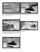
MOUNT THE ENGINE NOTE: The engine in your airplane is mounted slightly different from that of most R/C aircraft. This is done to allow the use of many different types of engines. It also allows a “no-drill” approach to ease the engine installation. Read through the procedure and understand all the steps before actually performing them. ❍ 1. To complete this step you will need the following items as shown in the photograph above.
❍ 4. With the engine in place, install the remaining two 4mm x 25mm machine screws, 4mm lock washers, and 4mm nuts in place at the front of the engine mount as shown in the photograph. Do not tighten the screws at this time to allow for the positioning of the engine. ❍ 7. Attach the silicone fuel lines to the engine. The line you marked “Vent” should be attached to the muffler. The other line will be attached to the needle valve. Make sure there are no sharp bends in the lines.
MOUNT THE LANDING GEAR ❍ 1. To complete this step you will need the following items as shown in the photograph above. #1 #2 #3 #4 #5 #6 #7 #8 #9 #10 #11 #12 #13 #14 of the fuselage. If they will not go in easily, drill out the two holes using a 5/32” [4mm] drill bit. Next, use the drill bit or hobby knife to bevel the inside corners of the holes so that the bend in the wire will seat fully into the holes and the wire will be flush with the bottom of the fuselage.
photograph. Place the washer on the threaded stem followed by the wheel-type nut. Apply Threadlocker to the threaded stem and then gently tighten the nut. It is important not to overtighten this nut; this would not allow the screw lock pushrod connector to rotate on the steering arm while in operation. Adjust the tightness of the nut and test the connector’s ability to rotate but still be somewhat tight.
FINAL ASSEMBLY To complete this step you will need the following items, as shown in the photograph above. #1 #2 #3 #4 #5 #6 #7 #8 Protective Foam (2) Faslinks (2) Screw Lock Pushrod Connector (1) Silicone Clevis Retainers (3) Clevises (3) Control Horn Backplates (2) Control Horns (2) 2mm x 14mm Phillips Head Screws (4) #9 680mm Threaded Elevator-Rudder Pushrods (2) #10 Battery/Receiver Tray (1) #11 2.
HOOK UP THE CONTROLS ❍ 4. Screw two nylon clevises 25 full turns onto the two 680mm threaded wire pushrods. Slip silicone retainers over the clevises. ❍ 1. There is a 5mm hole in the firewall for the pushrod guide tube that will align with the throttle arm on most twostroke engines. Use medium sandpaper to roughen both plastic pushrod guide tubes. Insert one pushrod guide tube through the hole in the firewall for the throttle, and the other for the steering pushrod guide tube.
INSTALL THE RADIO GEAR Elevator Arm Throttle Arm Rudder/Steering Arm ❍ 1. You must modify 3 servo arms to be used in this section. Starting with the 4 armed servo arms supplied with your radio system, modify them exactly as shown in the above illustration. Enlarge the holes in the locations shown with a Hobbico Servo Horn Drill (or a #48 or 5/64" [2mm] drill bit). Note: You may wish to trim the excess material from the arms as shown in the illustration and the following photographs. ❍ 4.
❍ 6. Carefully align the nose wheel as straight as possible. Align the steering pushrod with the second hole (out from the center) in the rudder servo arm and place a mark on the steering pushrod as shown in the above photograph. As you did with the previous pushrods, make a 90-degree bend at the mark, install the servo arm and the Faslink, and cut off the excess steering push rod. Put the rudder/nose gear steering arm on the servo with the screw. ❍ 8.
❍ 12. Make a pushrod guide tube support by using the supplied 10mm x 13mm x 80mm balsa material. Place it into the fuse as shown in the photograph above and mark the locations of the throttle and steering guide tubes. Cut, sand, or file a V or notch at these locations. Use sandpaper to roughen the outer surface of the tubes where they meet the guide tube support. Reposition the guide tube support making sure the tubes rest in the notches and do not bind or put pressure on the pushrods.
PREPARE THE MODEL FOR FLIGHT Now move the throttle stick forward to full. Make sure that the carburetor barrel opens all the way. If it doesn’t open far enough or opens too far [bending the rod] move the pushrod and screw lock pushrod connector in or out on the servo arm and/or the clevis on the carburetor arm to gain or reduce movement. The throw will be correct when the carburetor barrel will stop fully open at the same time the throttle stick reaches full.
Balance the Model (C.G.) Begin by placing incrementally increasing amounts of weight on the fuselage over the firewall until the model balances. Once you have determined the amount of weight required, it can be permanently attached. If required, tail weight may be added by cutting open the bottom of the fuselage and gluing it permanently inside. More than any other factor, the C.G.
PREFLIGHT Ground Check If the engine is new, follow the engine manufacturer’s instructions to break-in the engine. After break-in, confirm that the engine idles reliably, transitions smoothly and rapidly to full power and maintains full power— indefinitely. After you run the engine on the model, inspect the model closely to make sure all screws remained tight, the hinges are secure, the prop is secure and all pushrods and connectors are secure.
CHECKLIST Do not use your fingers to flip the propeller. Make certain the glow plug clip or connector is secure so that it will not pop off or otherwise get into the running propeller. During the last few moments of preparation your mind may be elsewhere anticipating the excitement of the first flight. Because of this, you may be more likely to overlook certain checks and procedures that should be performed before the model is flown.
GETTING READY TO FLY IMPORTANT!!! Flying a model with too few rubber bands can be dangerous. If the wing momentarily lifts from the fuselage and acts as though a large amount of “up” elevator has suddenly been applied because there are not enough rubber bands or they are too weak, internal structural damage may result. Even worse, the wing could actually detach from the fuselage resulting in a crash.
TAKEOFF Your first flight should be made in little or no wind. If you have dual rates on your transmitter, set the switches to “low rate” for takeoff. Taxi into position, pointing directly into the wind. Although this model has good low speed characteristics, you should always gain as much speed as your runway will permit before lifting off, as this will give you a safety margin in case of a “flame-out”. Advance the throttle smoothly to the wide-open setting.
MODELING TERMS AND TRIVIA is advisable to mount the charge jack in an accessible area of the fuselage so an ESV can be used without removing the wing. Adverse Yaw - The tendency of an airplane to yaw in the opposite direction of the roll. For instance, when right aileron is applied, the airplane yaws to the left, thus opposing the turn. Adverse yaw is common in trainer type airplanes having flat bottom wings.
produce more aerodynamic lift from the wing, allowing a slower takeoff and landing speed. Flaps are often found on scale models, but usually not on basic trainers. Grease-In - A very smooth, gentle landing without a hint of a bounce. Hit (or to be hit) - Sudden radio interference which causes your model to fly in an erratic manner. Most often caused by someone turning on a radio that is on your frequency, but can be caused by other radio sources miles away.
Prop Pitch - Props are designated by these two numbers, for instance 10 - 6. The first number is the prop’s length, 10". The second number is the pitch or angle of the blades. The 6 represents the distance the propeller will move forward in one revolution, in this case 6". Tip Stall - The outboard end of one wing (the tip) stops developing lift, causing the plane to roll suddenly in the direction of the stalled wing. This situation is not fun when you are only a few feet off the runway trying to land.
Fill out the ID tag below and tape it in your model. We have included a spare tag. PARTS LIST Before assembly match the parts in the photo with the parts in the kit. Check off each part as they are located. If any parts are missing or damaged, consult Tower Hobbies Order Assistance (see phone numbers listed on the front page). Note: All parts are one per kit unless otherwise stated.
Hobbico® DC Quick Field Charger (HCAM3000) Tower Hobbies® 4-TH 4-Channel FM (TOWJ41**) Fast-charge radio batteries anywhere. Take advantage of today’s best FM technology. Recharge 9.6V transmitter and 4.8V or 6.0V receiver batteries right on the spot, using any 12V DC input. Advanced Delta peak sensing technology automatically switches to trickle once batteries are fully charged. Unique voltage boost circuitry peaks transmitter NiCds even in diode-equipped radios. Includes 2.