
Operating instructions

2020
Appliance Preparation
Stand-off and Support Angles Installation
and Fitting
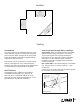
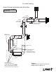
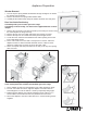
The distance from the support angles to the front face
of the heater case is adjustable to allow for a range of
wall fi nish material thickness (e.g. tile, etc.).
1. Check the wall fi nish requirements with the
homeowner.
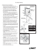
2. Secure the side support angles from the inside of
the appliance using two screws provided. Set back
the support angles from the front of the appliance
by the thickness of the wall fi nish + 3/4” (19 mm) for
projection.
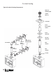
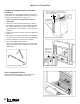
3. Remove two screws from the rear of the appliance’s
frame top.
4. Bend the 12-inch stand-off and fi x it to the appliance
case with the two screws just removed as indicated.
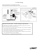
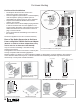
5. Place the appliance in position in the framing.
6. Secure the appliance to the studs.
Note: The support angles screws may be loosened
later from the inside of the appliance to make fi nal
adjustments.
Fit screws
from inside
case
Thickness of wall nish + extra 3/4” (19 mm)
(Appliance MUST project 3/4” (19 mm) in front
of the wall nish surface)
Fix to appliance
case with
two screws
Support angles
adjustment
from inside
of the appliance
12-inch stand-off supplied fl at
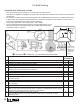
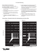
Rear Log Support Removal
Remove the rear log support to access to the rear
orifi ces for restrictors installation (5 screws).
Remove rear log support
Support angles fi tting
Support angles and stand-off install