
Operating instructions

1616
40
38
36
34
32
30
28
26
24
22
20
18
16
14
12
10
8
6
4
2
40
38
36
34
32
30
28
26
24
22
20
18
16
14
12
10
8
6
4
2
2 4 6 8 10 12 14 16
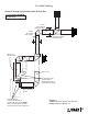
Rear outlet
Top outlet
1
1
2 4 6 8 10 12 14 16
1
35
35
0.5
1
2
3
12 3
0.5
1
2
3
12 3
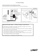
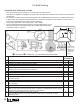
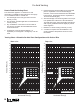
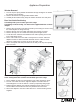
How to Read the Venting Chart
The chart below applies to co-axial roof or wall
termination in installations with vertical rise. See page
13 for installations with no vertical rise.
1. The total length of the vent pipe cannot exceed
40 feet (12.2 m).
2. The minimum vertical height with roof termination is
10 feet (3.05 m).
3. Any combination of rise and run can be used as
long as they are within the allowable limits shown
on the chart below.
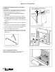
4. A maximum of four 90 degrees elbows—or
equivalent (2 x 45 degrees = 90 degrees)—can be
used.
5. Each 90 degrees elbow installed on the horizontal
plane is equivalent to a 3 feet horizontal pipe;
therefore, 3 feet must be subtracted from allowable
horizontal run. (45 degrees elbow is equivalent to
18 inches horizontal pipe.)
6. All horizontal pipe runs must be graded 1/4 inch per
foot upwards in the direction of the exhaust fl ow.
The fi nal pipe length, when terminating through the
wall may be graded downwards slightly to prevent
water migration.
7. Maximum co-linear venting is 40 feet (12.2 m).
8. A restrictor is required for all installations—see
section Appliance Preparation section for more
information.
Vertical Rise (ft)
Vertical Rise (ft)
Horizontal Run (ft) Horizontal Run (ft)
NO INSTALLATION
NO INSTALLATION
NO INSTALLATION
NO INSTALLATION
Venting Chart—Allowable Co-Axial Vent Confi gurations with Vertical Rise
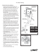
Example 1
Co-Axial Venting