L2 SERIES DV ZC Gas Fireplace 1700IN (NG) & 1700IP (LPG) Installation & Owner’s Manual ! DANGER HOT GLASS WILL CAUSE BURNS. DO NOT TOUCH GLASS UNTIL COOLED. NEVER ALLOW CHILDREN TO TOUCH GLASS. A barrier designed to reduce the risk of burns from the hot viewing glass is provided with this appliance and shall be installed for the protection of children and other at-risk individuals.
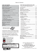
Table of Contents FOR THE OWNER FOR THE QUALIFIED INSTALLER Safety Precautions .......................................... 3 Safety and Your Fireplace ............................... 4 Owner’s Information........................................ 5 Commonwealth of Massachusetts............... 17 Specifications ................................................ 19 Overview......................................................... 20 Dimensions & Location.................................
! Safety Precautions READ and UNDERSTAND all instructions carefully before starting the installation. FAILURE TO FOLLOW these installation instructions may result in possible fire hazard and will void the warranty. Prior to the first firing of the fireplace, READ the Owner’s Information section of this manual. DO NOT USE this appliance if any part has been under water.
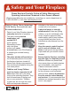
! Safety and Your Fireplace Safety and Your Fireplace Please Read and Carefully Follow all Safety Warnings and Operating Instructions Contained in Your Owner’s Manual (Replacement Manuals are available by contacting our service department at 1-800-468-2567 or visit www.valorfireplaces.com). Please Follow These Important Child Safety Precautions and Recommendations, 4 • Parts of your Valor Fireplace become extremely hot while in operation.
Owner’s Information ! WARNING EXTREMELY HOT!!! • READ the SAFETY information on pages 3 and 4 of this manual BEFORE operating your gas heater. • Some parts of your fireplace are EXTREMELY HOT, particularly the GLASS window. • DO NOT LET CHILDREN touch the glass or any parts of your fireplace even after it is turned off as it is still hot. • USE THE BARRIER SCREEN provided with the trim or a GATE to reduce the risk of severe burns. • Keep the remote control handset OUT OF REACH of children.
OWNER’S INFORMATION Owner’s Information Cleaning Your Fireplace ! WARNING DO NOT TOUCH THE GLASS WHILE IT IS HOT! Let the fireplace cool first before cleaning it. Important - Glass cleaning - Mineral deposits One of the by-products of the combustion process in a gas appliance is a mineral which can show up as a white film on the ceramic glass of the viewing door. The composition of the deposit varies with location and time. It is believed to be associated with the varying sulfur content of the gas.
OWNER’S INFORMATION Owner’s Information applied to the surface, no alcohol/solvent based cleaning agents nor polishes should be used. Dry stains can be removed using a white or light colored cloth with mild soap and warm water when the material is cool, then dried immediately. If the stain is hard to remove, use a white or light colored synthetic scrub pad (not steel wool) and dry immediately.
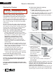
OWNER’S INFORMATION Owner’s Information The appliance area must always be kept clear and free from combustible materials, gasoline and other flammable vapors and liquids. Inspect the vent terminal outdoors regularly to make sure that snow, trees, bushes, leaves, or other objects do not obstruct it. Examine the vent system and terminal regularly. We recommend annually. 2. Slide battery carrier to ease access.
OWNER’S INFORMATION Owner’s Information How to Turn Your Fireplace OFF (including pilot) Data plate Window The rating plate is located behind the front panel of the appliance towards the right-hand side. To access the plate, remove the barrier screen, side doors and the plinth. Grab the return edge of the plate and slide it out of its rails. There is important information on both sides of the plate.
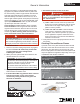
OWNER’S INFORMATION Remote Control Operation NOTE: Before using the remote control system for the first time, the receiver and the handset must be synchronized. See the section Remote Control Initial Set-up on page 49 of this manual. Current temperature (F or C) IMPORTANT: BEFORE YOU BEGIN, please note that on this system, the settings of time, temperature and automatic ON/OFF can only be programmed when the function display is flashing. Be patient when programming as it can take a few seconds to set.
OWNER’S INFORMATION Remote Control Operation • Press and hold (small flame) button to decrease flame height or to set the appliance at pilot flame. • For fine adjustment tap the (large flame) or (small flame) buttons. MODES OF OPERATION • Briefly pressing the SET button changes the mode of operation in the following order: MAN → Express Low and High Fire • Double-click (small flame) button. “LO” will be displayed. NOTE: Flame goes to high fire first before going to designated low fire.
OWNER’S INFORMATION Remote Control Operation SETTING THE ON / OFF TEMPERATURES SETTING THE “DAYTIME” TEMPERATURE SETTING THE “NIGHTTIME SETBACK” TEMPERATURE Default Settings: Default Settings: • TEMP (sun), 23ºC / 74ºF Briefly press SET button to scroll to TEMP TEMP (sun) mode. Hold the SET button until the TEMP flashes. TEMP (moon), “--” (OFF) • Briefly press SET button to scroll to TEMP T E M P (moon) mode. Hold the SET button until the TEMP flashes.
OWNER’S INFORMATION Remote Control Operation SETTING PROGRAM TIMERS SETTING P1 OFF TIME • You can program two periods of time between 12:00 am and 11:50 pm in each 24-hour cycle. • The Programs P1 and P2 must be set in the following order during a 24-hour cycle: P1 , P1 , P2 and P2 . • The icon indicates the beginning of the period (ON) and the icon indicates the end of the period (OFF). • If P1 = P1 or P2 = P2 , the programming is cancelled.
OWNER’S INFORMATION Remote Control Operation Timer Programming Example (default temperatures shown) 6:00 a.m.— P1 Start time ☼ Set temp 4:00 p.m.— P2 Start time 8:00 a.m.— P1 ☽ End time ☼ 74˚F Set temp 10:00 p.m.— P2 ☽ End time ☼ ☽ 40˚F Set temp ☼ 74˚F Set temp 6:00 a.m.— P1 Start time ☼ ☽ 40˚F AUTOMATIC TURN DOWN • No communication. If there is no communication between the receiver and the handset for a period of 6 hours, the appliance goes into pilot mode.
OWNER’S INFORMATION Wall Switch Operation The Wall Switch can be used to control your fireplace. You can turn the pilot on or off and you can increase or decrease the flame height. TO ADJUST FLAME HEIGHT • Press and hold large flame button to gradually increase flame height. Note that the thermostat and programming functions are not available with the wall switch. TO TURN APPLIANCE ON and OFF • • Press ON-OFF button once to light pilot. Press again to shut of pilot.
OWNER’S INFORMATION Lighting Instructions FOR YOUR SAFETY, READ BEFORE LIGHTING WARNING: If you do not follow these instructions exactly, a fire or explosion may result causing property damage, personal injury or loss of life. A. This appliance has a pilot which must be lighted by hand, remote control, or wall switch. Follow these instructions exactly. To save gas, turn the pilot off when not using the appliance for a prolonged period of time. B.
Commonwealth of Massachusetts State of Massachusetts Carbon Monoxide Detector/Vent Terminal Signage Requirements For all side wall horizontally vented gas fueled equipment installed in every dwelling, building or structure used in whole or in part for residential purposes, including those owned or operated by the Commonwealth and where the side wall exhaust vent termination is less than seven (7) feet above finished grade in the area of the venting, including but not limited to decks and porches, the follow
QUALIFIED INSTALLER Commonwealth of Massachusetts (d) MANUFACTURER REQUIREMENTS - GAS EQUIPMENT VENTING SYSTEM NOT PROVIDED. When the manufacturer of a Product Approved side wall horizontally vented gas fueled equipment does not provide the parts for venting the flue gases, but identifies “special venting systems”, the following requirements shall be satisfied by the manufacturer: 1.
Specifications Approval & Codes This appliance is certified to ANSI Z21.88-2014/ CSA 2.33-2014 American National Standard / CSA Standard for Vented Gas Fireplace Heaters for use in Canada and USA, and to CGA 2.17-91 High Altitude Standard in Canada. This appliance is for direct vent installations. This appliance complies with CSA P4.1-09 Testing method for measuring annual fireplace efficiencies.
QUALIFIED INSTALLER Overview Fire On/Off Wall Switch (20-foot wire length) (supplied, recommended) Mantel—See Mantel & Hearth Clearances Framing—See Framing Requirements Remote Handset Wall Holder 1/2 inch thick non-combustible cement board – NOT supplied Surround d Platte wiit ith ith Barrrier Screen (required) Narrrow 1” Trim 1755LFB and wider 5-1/4” steel Trim 1750 adjustable, accept additional nonco ombustible finish over cement board and behind trim; Supplied as vertical outlet, field convertibl
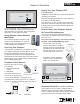
QUALIFIED INSTALLER Dimensions & Location Dimensions 57.3/4” (1467 mm) Center Line 15-3/16” (386 mm) 18.1/8” (460 mm) 20” (508 mm) 52” (1321 mm) Heat shield required for rear vent outlet applications 18-5/8” (473 mm) 1515-3/16” (386 6 mm) Top View Zero Clearance Stand-Offs 6-5/8” dia. Venting fieldconvertible from top to rear outlet Header 3-3/4” (95 mm) 1270RBK Duct Kit Inlet Gas Line (remove plate) Access Point Left Side View 33-1/8” (841 mm) Min.
QUALIFIED INSTALLER Mantel & Hearth Clearances Combustible Mantel—Left Side View Ceiling Mantel Projection (from Face of Cement Board) 44” 42” 40” 38” Mantel Height (from Bottom of Unit) Face of 1/2” thick non-combustible cement board 23-7/8” Fireplace Opening Do not put furniture or objects within 36” (914 mm) of front of appliance 4” minimum to combustible or non-combustible hearth 9-3/8” Bottom of Unit 22 24” Min.
Mantel & Hearth Clearances QUALIFIED INSTALLER Combustible Sidewall / Mantel Leg—Top View FIREPLACE Face of Finished Wall Fireplace Opening 49-11/16” Wall Min.
QUALIFIED INSTALLER Framing Requirements Framing Dimensions 1/2” thick non-combustible cement board required above, on each side and below engine opening (NOT supplied) NOTE: Height of cavity may be affected by vent configuration - see page 26 NOTE: This unit requires a solid platform to support it. Combustible framing allowed beneath fireplace.
QUALIFIED INSTALLER Framing Requirements Framing with Partial Shelf—Top Outlet Fireplace Opening 14-1/2” (369 mm) 1/2” thick non-combustible Cement Board 9-3/8” (238 mm) Min. 1” (25.4 mm) clearance to combustibles around vertical vent pipe 43” (1093 mm) to underside of combustible cavity 19-1/4” (489 mm) 15-3/16” (386 mm) Approx.
QUALIFIED INSTALLER Framing Requirements Venting Considerations—Vertical Takeoff *Notes—ALL venting considerations 43” (1093 mm) to underside of combustible cavity 19-1/4” (489 mm) 14-1/2” (369 mm) Fireplace Left Side View 9-3/8” (238 mm) Min 1” (25.4 mm) Required clearance to vertical pipe is within stand-off space Stand-off 37” (940 mm) *45” (1143 mm) *55-1/2” (1410 mm) with 12” vent pipe 12” pipe section • Dimensions of venting are based on using Dura-Vent elbows.
QUALIFIED INSTALLER Venting Top or Rear Outlet This unit is supplied with a top vent outlet which can be field-converted to a rear vent outlet. See Appliance Preparation section for more information. Vent Material This unit is approved for installation using 4 x 6-5/8 inches co-axial direct vent pipe and accessories as listed in the Approved Venting Components section on pages 53–54 of this manual. Follow the installation instructions supplied with the individual venting accessories.
QUALIFIED INSTALLER Co-axial Venting Typical Co-axial Venting Components HORIZONTAL TERMINATION 2-PIECE WALL THIMBLE VERTICAL TERMINATION 90˚ ELBOW PIPE LENGTH STORM COLLAR PIPE LENGTH FLASHING 90˚ ELBOW ATTIC INSULATION SHIELD HORIZONTAL TERMINATION ATTIC FIRESTOP CEILING FIRESTOP 2-PIECE WALL THIMBLE Rear Vent PIPE LENGTH PIPE LENGTH 90˚ ELBOW PIPE LENGTH PIPE LENGTH Top Vent 28 Top Vent
QUALIFIED INSTALLER Co-axial Venting How to Read the Venting Chart be used. Excludes the 45 degrees take-off elbow shipped with the appliance. 6. Each 90 degrees elbow installed on the horizontal plane is equivalent to a 3 feet horizontal pipe; therefore, 3 feet must be subtracted from allowable horizontal run. (45 degrees elbow is equivalent to 18 inches horizontal pipe.) 7. All horizontal pipe runs must be graded 1/4 inch per foot upwards in the direction of the exhaust flow.
QUALIFIED INSTALLER Co-axial Venting Restrictor The restrictor is located in the roof of the firebox hidden above the top liner panel. Adjust the restrictor before installation of the top liner panel. Should subsequent adjustment be required, you will need to remove the top liner panel—see page 41. ALL INSTALLATIONS REQUIRE A RESTRICTOR for improved flame picture and performance. This unit is supplied with a pre-fitted restrictor having five different positions or settings.
QUALIFIED INSTALLER Co-axial Venting Vent Termination • The vent terminal must be located on an outside wall or through the roof. • This direct vent appliance is designed to operate when an undisturbed airflow hits the outside vent terminal from any direction. • The minimum clearances from this terminal that must be maintained when located on an outside wall are shown in the figure below. Any reduction in these clearances could result in a disruption of the airflow or a safety hazard.
QUALIFIED INSTALLER Co-axial Venting Vertical Vent Termination Roof Pitch Flat to 7/12 Horizontal overhang Minimum "H" (feet) 1' Over 7/12 to 8/12 1.5' Over 8/12 to 9/12 2’ Over 9/12 to 10/12 2.5’ Over 10/12 to 11/12 3.25’ Over 11/12 to 12/12 4’ Over 12/12 to 14/12 5’ Overhang should not extend beyond vent if within 48” of termination cap Termination cap Vertical wall Min. 24” (unvented soffit) Min. 36” (vented soffit) Min.
QUALIFIED INSTALLER Co-linear Venting 1156CLA Co-Linear Vent Adapter 8-5/8” FRONT REAR 52” 11-11/16” 9-3/8” 3” exhaust collar 3” intake 4” exhaust collar on the centerline 4” 4” exhaust collar adapter 1-1/2” 32-3/8” Dimensions with co-linear adapter Dimensions shown are with Valor 1156CLA co-linear adapter. Installation For installation of the adapter to the appliance, see the instructions supplied with the 1156CLA.
QUALIFIED INSTALLER Installation Planning Installer—READ THIS FIRST Only qualified licensed or trained personnel should install this appliance. 1. YOU NEED TO KNOW FROM THE HOMEOWNER: - The height of the unit and hearth if used; - The thickness and type of the wall finish around the firebox opening; - What accessories (trim, decorative lighting, etc.) will be installed with this fireplace; - The venting configuration. 2. Unpack the appliance, removing all items packed inside and around the appliance. 3.
QUALIFIED INSTALLER Installation 3. Taking great care not to cut your hands on the sheet metal edges, lift the appliance out of its packing base and place it in the framing. Make sure that the unit is at the right height with consideration to the height of the hearth or combustible flooring. 4. Remove the heat shield from the top of the appliance case (3 screws). If using the top outlet, discard the shield.
QUALIFIED INSTALLER Installation Plan Wall Finish Non-combustible cement board The L2 Linear fireplace requires a 1/2” (13 mm) thick non-combustible cement board to be used as a wall surface immediately surrounding the unit on each side—see diagram below for minimum coverage. Extending the cement board well beyond the minimum shown will help avoid cracking due to differential expansion of materials.
Installation Cracking If a clean finish with no tile, etc. is desired, joints in the cement board and the transition to gypsum board will require special attention if future cracking is to be controlled. Be aware that temperatures on the noncombustible wall surface above the appliance can exceed 200°F. Below are some tips on how to best avoid any cracking: • Allow materials to dry thoroughly before finishing the wall.
QUALIFIED INSTALLER Installation Install Electrical Wiring (for optional accessories) This section provides information to install the electric pre-wiring required for use with the 1595CFK Circulating Fan Kit and/or the 1565LLK Lighting Kit. All wiring must be done by a qualified electrician in accordance with local codes or, in the absence of local codes, with the National Electrical Code, ANSI/ NFPA 70 or the Canadian Electrical Code, CSA C22.1.
QUALIFIED INSTALLER Installation 7. Pull the excess cable back through the cable clamp and tighten the locking ring to the cable clamp. Alternate clamp without locking ring may be used - ensure the proper clamp is used for the type of cable used. 8. Tighten cable clamp on outside of fireplace casing and secure and excess wire to framing. Set-up Gas Supply The gas supply inlet connection is a 3/8” NPT male connector located on the left hand side of the firebox.
QUALIFIED INSTALLER Installation Pressure test the supply line for leaks. The appliance and its individual shut-off valve must be disconnected from the gas supply piping system during any pressure testing of that system at test pressures in excess of 1/2 psig (3.5 kPa).
Installation Install Liners The liners install in the manner outlined below with the exception of the 1725RGL—Reflective Glass Liners: see instructions supplied with the liners. Unpack the liner panels carefully. 1. Inside the firebox, on the top of each side, release the screw of the side panel anchors (one per side) QUALIFIED INSTALLER Place the panel’s right section on the ledge above the ports of the rear of the firebox.
QUALIFIED INSTALLER Installation 6. Place rear panel’s centre section on the ledge behind the tabs, slide it to the right so that its stepped edge fits into the stepped edge of the rear panel’s right section. 7. Place the left side panel against the left wall of the firebox. 8. Tighten the side panel anchors on each side of the firebox 9. Place the remaining rear panel’s section behind the left side panel and fit its stepped edge to the stepped edge of the rear panel’s center section. 42 10.
QUALIFIED INSTALLER Installation Install Long Beach Driftwood Kit Material required • Middle platform brackets (supplied with appliance) • Vermiculite platform (supplied with appliance) • Small container to distribute vermiculite (not supplied) • Long Beach Driftwood Kit, which contains: ◊ 6 logs ◊ 10 pebbles ◊ 1 bag of vermiculite Installation Platform Carefully unpack the kit. 1.
QUALIFIED INSTALLER Installation Logs and rocks Each log has pegs to help you locate them on the platform. Install the logs as shown below. 1. Place the rear log in the center of the firebox at the rear. NOTE: There are two holes for the left peg of this log depending which type of gas is used for the appliance. NG fire: Place the log’s left peg in the front hole for natural gas (NG) fire. LPG fire: Place the log’s left peg in the rear hole for propane gas (LPG) fires. 4.
QUALIFIED INSTALLER Installation 6. Place centre cross log to rear log as indicated. Pivot tail end so tip is just inside fireplace window line. 7. Some vermiculite may be added outside the burner on the platform if desired. 8. Place the rocks on the platform as shown below. You can also place one or two rocks on the vermiculite as shown. ! WARNING CHOKING HAZARD! Ensure that the fireplace area is clear of vermiculite particles as these could be ingested by small children. Vacuum area after installation.
QUALIFIED INSTALLER Installation 2. Install the sheet metal platform on top of the brackets as indicated. The edge of the burner protrudes above the platform. Push the platform as far back as possible to maximize the air gap behind the burner. Gap behind burner 4. Mix the black and blue fire glass together. 5. Fill a small container with approximately 3 cups (750 ml) of mixed fire glass. 6.
Installation QUALIFIED INSTALLER Refit Window 1. To refit the window, place it in its bottom railing and push its top against the firebox. Ensure there is no glass or vermiculite particles in the bottom railing. 2. While you hold it, pull the side levers back into the window brackets on each side. IMPORTANT: To ensure a safe operation, verify that the levers are hooked properly to the window tabs; then, pull out the top of the window and release it to insure the springs return it.
QUALIFIED INSTALLER Installation Install Wall Switch Kit (recommended) CAUTION DO NOT PUT BATTERIES IN THE REMOTE CONTROL RECEIVER OR THE BATTERY BOX until the wires are connected to the burner control unit as short-circuit could result in the destruction of the electrical components. The wall switch kit is provided with this appliance. It is connected to the receiver in the fireplace. The receiver is located on the left side of the appliance, left of the control valve behind the appliance’s front panel.
QUALIFIED INSTALLER Installation 8. Disconnect the battery box wire if already connected. 9. Remove the cover of the battery box (1 screw). 10. Insert four AA alkaline batteries in the battery box, refit the cover and secure with the screw. Note: Do not put batteries in the receiver, only in the battery box. 11. Reconnect the battery box and place it back in its carrier. 12. Slide the carrier towards the right hand side so that the battery box goes outside of the appliance case. 13.
QUALIFIED INSTALLER Installation Check Operation Turn the fireplace flame up and down using the remote control to confirm that the full range of inputs is achieved—see the remote control operation instructions on pages 10–14. Set Aeration (if necessary) Light the fire and allow the unit to warm up for 10–15 minutes to evaluate the flame picture. The burner is equipped with an adjustable shutter to control primary aeration (NG only).
Installation QUALIFIED INSTALLER Install Remote Control Handset Wall Holder The remote control kit for this fireplace comes Alternative 2 Packing Contents: complete with a wall-mounted holder. This 1 Wall Bracket A holder is not required in all installations but 2 Screws B is provided as an optional feature for those 1 Screw C customers who wish to mount the remote 2 Wall Anchor D 1 Spacer E handset to the wall.
QUALIFIED INSTALLER Wiring Diagram Wall Switch Kit Connector Remote Battery Box 4 AA Batteries GV60 Wiring Diagram 52
QUALIFIED INSTALLER Approved Venting Components Approved Direct Vent Suppliers for Valor Models 1100, 1150, 12005, 1500, 16005 and 17006 DURA-VENT SELKIRK ICC EXCEL DIRECT SECURE VENT RLH INDUSTRIES AMERIVENT MILES INDUSTRIES BDM Venting Parts Code / availability by Manufacturer Standard Co-axial 46DVA-HC 4DT-HC TM-4HT — — 4DHC round 658DVK 940160 Deluxe Co-axial — — TM-4DHT — — 4DHCS square — 940160 High Wind Co-axial — — — SV4CHC — — — Horizontal Venting Parts Descrip
QUALIFIED INSTALLER Approved Venting Components 4DT-06 TC-4DL6 SV4L6 Black 46DVA-06B 4DT-06(B) TC-4DL6B SV4LB6 Pipes 4” x 6 5/8” ( ID x OD ) 7” long 9” long 12” long 18” long 24” long Flashings Various Venting System Parts — Galvanized 46DVA-09 4DT-09 — — — — — — Black 46DVA-09B 4DT-09(B) Galvanized 46DVA-12 4DT-12 TC-4DL1 SV4L12 Black 46DVA-12B 4DT-12(B) TC-4DL1B SV4LB12 — — Galvanized 46DVA-18 4DT-18 Black 46DVA-18B 4DT-18(B) — Galvanized 46DVA-24 4DT-24
OWNER’S INFORMATION WA TY N A RR M GR A O PR T LOR OR If you have a problem with this unit, please contact your dealer or supplier immediately. Under no circumstances should you attempt to service the unit in any way by yourself. The warranties in paragraphs 1 and 2 are provided only to the first purchaser/user of this unit, are not transferable and are subject to the conditions and limitations in paragraphs 3, 4 and 5.
OWNER’S INFORMATION Code Spare Parts Description Part Number Code 4003049 38 Thermocouple interrupter 4001037 0945M 39 Pipe s/s flex 4000345 Description Part Number 1 Heat shield 2 45 degrees flanged elbow 3 Elbow gasket 4002999 40 Handset wall holder 9000008 4 Top stand-offs (2) 4002985 41 Handset G6R H3T5-ZV (BJ) 4001910 5 Restrictor plate 4003017 42 Receiver G6R-R3AM-ZV (CP) 4001911 6 Take-off cover (2) 4003046 43 Wire harness GV60 4001187 7 Battery slder assem
Spare Parts Code Description OWNER’S INFORMATION Part Number 62 LH front log 4002967 63 Center cross log 4003721 64 RH rear log 4003928 65 RH Cross log 4003929 66 Brown beach pebble 4003082 67 Grey beach pebble (2) 4003083 68 Small grey beach pebble 4003086 69 White beach pebble (2) 4003084 70 Black beach pebble (2) 4003085 71 Small beige beach pebbles (2) 4003087 72 Grade 1A vermiculite, bagged 4002940 73 Hot glass warning plate 4003093 57
OWNER’S INFORMATION Spare Parts 1 55c 55e 58 55f 55a 2 55b 55e 56 55f 57 55d 3 5 4 54 60 59 63 61 13 64 8 62 66 67 73 65 68 69 70 71 6 10 72 9 14 11 43 42 7 12 40 41 44 16 45 53 17 15a, 15b 18 49 19 46 25-26 20-24 35 51 50a 53 50 32 39 50a 47 48 36 33 52 34 38 37a, 37b 58 27 28a, 28b 29 30 31
Thank You ... For purchasing a Valor by Miles Industries. Your new radiant gas heater is a technical appliance that must be installed by a qualified installer. Please fill in the information below. The information provided will be used for customer records only.
Tape Shut Fold here Postage needed Miles Industries Ltd. 190 - 2255 Dollarton Highway North Vancouver, BC V7H 3B1 Canada Online Warranty registration at www.valorfireplaces.