
Instruction Manual

8
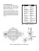
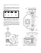
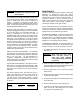
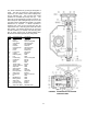
ITEM DESCRIPTION MATERIAL
1 Housing Cast Iron
2 Cover Cast Iron
3 Bushings Teflon / Fiberglass
4 Cover Bolts Stainless Steel
5 Gasket RTV Sealant
6 Indicator Cast Iron
7 Indicator Bolts Stainless Steel
8 Gasket RTV Selant
9 Lever Ductile Iron
9A Locking Pin Alloy Steel
10 O-Ring Buna-N
11 Retaining Ring Steel
12 Link Steel
13 Link Bushing Teflon / Fiberglass
14 Crosshead Bronze
15 Guides Bronze
16 Shaft Steel
17 Thrust Collar Bronze
18 Thrust Collar Pin Steel
19 Stop Nuts Steel
20 Stop Nut Pins Steel
21 Bevel Gear Cast Iron
22 End Cap Bolts Alloy Steel
33 Stem O-ring Buna-N
36 Handwheel Steel or Cast Iron
37 Pin Steel
39 Ball Bearings Steel
40 Bearing Race Steel
46 Stop Cover Cast Iron
47 Cover O-Ring Buna-N
48 End Cap O-ring Buna-N
50 Stop Cover Bolts Stainless Steel
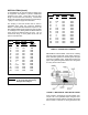
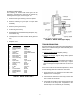
turn, drives a slotted lever (4) through 90 degrees of
travel. The lever (4) drives the valve shaft with a
square key. The rotation of the shaft is displayed by
the top indicator (19). The full open and closed
positions are controlled by the stop nuts (6). The
stop nuts can be adjusted by pounding out the pin (7)
with a drift punch and rotating the stop nut ½ turn. The
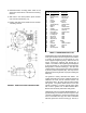
gear box is factory lubricated and sealed. No regular
maintenance is required. If difficult operation is
observed, the cover can be removed and the unit
inspected for wear. All moving parts should be coated
with grease. The grease should have an even and
smooth consistency. If needed, coat all moving parts
with an EP-2 grease such as Mobil Mobilux EP2.
Buried units should be packed 90% with grease.
TABLE 6. TRAVELING NUT ACTUATOR PARTS
FIGURE 9. TRAVELING NUT ACTUATOR
CONSTRUCTION