
Instruction Manual

9
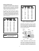
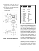
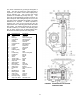
ITEM DESCRIPTION MATERIAL
21 Bevel Gear Hsg. Cast Iron
22 Mounting Bolts Steel
23 Cover Cast Iron
24 Cover Bolts Plated Steel
25 Gasket Composition Rubber
26 Bevel Gear Steel
27 Bevel Gear Key Steel
28 Pinion Gear Steel
29 Pinion Gear Key Steel
30 Spacer Steel
31 Input Shaft Type 416 SS
32 Retaining Ring Steel
33 O-Ring Buna-N
34 Bearing Bronze
35 2" Nut Cast Iron
37 Pin Steel
38 Thrust Washer Bronze
39 Needle Bearing Steel
40 Bearing Races Steel
41 Shims Steel
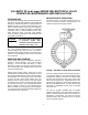
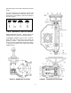
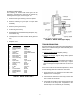
CHANGE OF ROTATION:
The traveling nut actuator with bevel gear can be
changed in the field from open-right to open-left by
inverting the bevel gear, refer to Figure 10.
1. Remove bevel gear housing cover and spacer.
2. Remove retaining ring and pull out input shaft
assembly.
3. Remove pinion gear and key.
4. Pull bevel gear and key.
5. Reassemble input shaft assembly with pinion, key,
and retainer ring.
6. Install spacer over shaft and then bevel gear and
key.
7. Replace cover.
TABLE 7. BEVEL GEAR PARTS
FIGURE 10. BEVEL GEAR (Open-Right)
TROUBLESHOOTING
Several problems and solutions are presented below to
assist you in troubleshooting the valve assembly in an
efficient manner.
Leakage at Valve Shaft: Replace packing.
Leakage at Flanges: Tighten flange bolts, replace
gasket.
Valve Leaks when Closed: Flush debris from seat by
cycling valve. Adjust actuator closed stop. Inspect
seat for damage and adjust seat bolts 1/4 turn at a
time.
If the valve continues to leak after adjustment, check
for the following items and make the corrections.
1. Verify that there is no damage to the rubber seat.
Replace if torn or damaged.
2. Check that the metal set in the body is clean and
free of scale and scratches.
3. Check that the actuator is fully closed and the seal
is centered in the body seat. Adjustment to the
actuator stop nuts or bolts may be necessary.