
User Manual


8
MAINTENANCE (Cont'd)
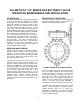
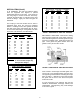
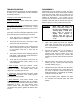
WORM GEAR ACTUATOR MAINTENANCE: A
typical worm gear actuator is shown in Figure 10
and consists of a worm (3) mounted on an input
shaft (9). The worm engages a segment gear (2).
When the worm is turned, it drives the segment gear
through 90° of rotation. The rotation of the segment
gear is displayed by the top indicator (5). The gears
are lubricated with EP2 grease in a cast iron housing
(1). The open and closed positions of the segment
gear (2) are controlled by the end position stop bolts
(20). The stops can be adjusted by loosening the
lock nut (21) and rotating the bolts (20).
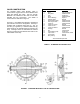
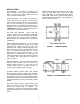
The gear box is factory lubricated and sealed. No
regular maintenance is required. If difficult operation
is observed, the cover can be removed and the unit
inspected for wear. All moving parts should be
coated with grease. The grease should have an
even and smooth consistency. If needed, coat all
moving parts with an EP-2 grease such as Mobil
Mobilux EP2. Buried units should be packed 100%
with grease.
FIGURE 10. GEAR ACTUATOR CONSTRUCTION
TABLE 4. WORM GEAR PARTS LIST
ITEM DESCRIPTION MATERIAL
1 Housing Cast Iron
2 Segment Gear Ductile Iron
3 Worm Alloy Steel
4 Cover Cast Iron
5 Indicator Cast Iron
6 O-Ring Buna-N
7 Thrust Bearing Carbon Steel
8 Bearing Bronze
9 Shaft Carbon Steel
10 Gasket Non-Asbestos
11 Handwheel Cast Iron
12 Operating Nut Cast Iron
13 Chainwheel Steel
14 Cover Bolt Carbon Steel
15 Indicator Bolt Steel
18 Worm Pin Steel
19 Handwheel Pin Steel
20 Stop Screw Steel
21 Jam Nut Steel
23 Oil Seal Steel & Rubber
Grease EP-2