VAL AVIONICS LTD INS 429 INTEGRATED NAVIGATION SYSTEM Installation and Operator’s Manual Original Issue August 2008 P/N 1720101
V A L A V I O N I C S L T D I N S 4 2 9 I N T E G R A T E D N A V I G A T I O N S Y S T E M I N S T A L L A T I O N A N D O P E R A T O R ’ S M A N U A L This Page Intentionally Left Blank Original Issue August 2008 Page 2 of 21
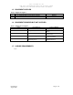
V A L A V I O N I C S L T D I N S 4 2 9 I N T E G R A T E D N A V I G A T I O N S Y S T E M I N S T A L L A T I O N A N D O P E R A T O R ’ S M A N U A L Table of Contents 1 2 3 4 5 6 7 SECTION I - GENERAL INFORMATION.......................................................................................4 1.1 INTRODUCTION............................................................................................................................ 4 1.2 SCOPE ...............................................
V A L A V I O N I C S L T D I N S 4 2 9 I N T E G R A T E D N A V I G A T I O N S Y S T E M I N S T A L L A T I O N A N D O P E R A T O R ’ S M A N U A L 1 SECTION I - GENERAL INFORMATION 1.1 INTRODUCTION Thank you for purchacing our INS 429 Integrated Navigation System. Here at Val Avionics Ltd., our core design philosophy is based on the ease of installation and use. The 429 represents 5 years of refinement in that process, based on the feedback of customers that have used the INS 422.
V A L A V I O N I C S L T D I N S 4 2 9 I N T E G R A T E D N A V I G A T I O N S Y S T E M I N S T A L L A T I O N A N D O P E R A T O R ’ S M A N U A L 1.4 SPECIFICATIONS Table 1: Specifications SPECIFICATIONS CHARACTERISTICS Environmental: (RTCA/DO160D) VOR Localizer Glide slope Marker Beacon RTCA/DO-196 RTCA/DO-195 RTCA/DO-192 RTCA/DO-143 Class B Physical Dimensions: Height Width Depth 3.40 inches (8.64 cm) 3.45 inches (8.76 cm) 9.87 inches (25.07 cm) Weight: 3.25 pounds (1.
V A L A V I O N I C S L T D I N S 4 2 9 I N T E G R A T E D N A V I G A T I O N S Y S T E M I N S T A L L A T I O N A N D O P E R A T O R ’ S M A N U A L 1.5 EQUIPMENT SUPPLIED Table 2: Equipment Supplied QTY DESCRIPTION 1 INS 429 INTEGRATED NAVIGATION SYSTEM 1 INSTALLATION KIT 1.6 EQUIPMENT REQUIRED BUT NOT SUPPLIED Table 3: Equipment Not Supplied QTY DESCRIPTION 1 Interconnect Wire Harness 1 Headphone Jacks 1.
V A L A V I O N I C S L T D I N S 4 2 9 I N T E G R A T E D N A V I G A T I O N S Y S T E M I N S T A L L A T I O N A N D O P E R A T O R ’ S M A N U A L 2 SECTION II - INSTALLATION 2.1 GENERAL INFORMATION 2.1.1 Scope This section of the manual will provide the needed information to successfully complete the installation of your new INS 429 Integrated Navigation System. Please read this section completely before proceeding with the installation process.
V A L A V I O N I C S L T D I N S 4 2 9 I N T E G R A T E D N A V I G A T I O N S Y S T E M I N S T A L L A T I O N A N D O P E R A T O R ’ S M A N U A L 2.3.3 Wire Harness Fabrication Val Avionics Ltd. recommends that a factory fabricated wire harness (VPN 0751030) be used for the installation of the INS 429 Integrated Navigation System.
V A L A V I O N I C S L T D I N S 4 2 9 I N T E G R A T E D N A V I G A T I O N S Y S T E M I N S T A L L A T I O N A N D O P E R A T O R ’ S M A N U A L 2.3.4.3 Audio The INS 429 has two audio outputs, Navigation audio and Marker audio. Although the audio output levels of the receivers are capable of driving a standard headset directly, it is strongly recommended that these audios be coupled to a quality audio selector panel such as a Val Avionics AP 100.
V A L A V I O N I C S L T D I N S 4 2 9 I N T E G R A T E D N A V I G A T I O N S Y S T E M I N S T A L L A T I O N A N D O P E R A T O R ’ S M A N U A L 3 SECTION III - OPERATION 3.1 GENERAL INFORMATION 3.1.1 Scope This section will provide detailed operating instructions for your new INS 429 Integrated Navigation System. Please read this section completely to become familiar with all of the features of the unit.
V A L A V I O N I C S L T D I N S 4 2 9 I N T E G R A T E D N A V I G A T I O N S Y S T E M I N S T A L L A T I O N A N D O P E R A T O R ’ S M A N U A L 3.1.3 User Controls Refer to Figure 1: Unit Controls. The user controls consist of two sets of concentric rotary knobs. The set on the left control functions on the left side of the display and the set on the right control the functions on the right side of the display.
V A L A V I O N I C S L T D I N S 4 2 9 I N T E G R A T E D N A V I G A T I O N S Y S T E M I N S T A L L A T I O N A N D O P E R A T O R ’ S M A N U A L 3.1.3.5 Selecting the Backcourse When ILS is displayed in the mode display pressing and holding the right inner knob for three seconds will enable the ILS in the back course mode and “BKCS” will be displayed in the Status display. While in the back course mode the glide slope VDI display will be flagged.
V A L A V I O N I C S L T D I N S 4 2 9 I N T E G R A T E D N A V I G A T I O N S Y S T E M I N S T A L L A T I O N A N D O P E R A T O R ’ S M A N U A L 3.2.1.3 External Mode When the Active Frequency display shows “Extern”, and the Standby shows “Mode”, the external mode function can be turned selected. When this function is “Off”, the frequency selection will rollover from 117 MHz to 108 MHz with no “Ext” shown in the frequency display.
V A L A V I O N I C S L T D I N S 4 2 9 I N T E G R A T E D N A V I G A T I O N S Y S T E M I N S T A L L A T I O N A N D O P E R A T O R ’ S M A N U A L 4 SECTION IV - WARRANTY AND SERVICE 4.1 LIMITED WARRANTY The equipment delivered with this Standard Factory Warranty is manufactured by Val Avionics, Ltd. and is guaranteed against defective materials and workmanship for one year from date of original retail purchase.
V A L A V I O N I C S L T D I N S 4 2 9 I N T E G R A T E D N A V I G A T I O N S Y S T E M I N S T A L L A T I O N A N D O P E R A T O R ’ S M A N U A L 5 Appendix A – INSTALLATION DRAWINGS AND CONNECTOR LAYOUT Figure 2: Physical Dimensions Figure 3: P1 Connector Pin Out Original Issue August 2008 Page 15 of 21
V A L A V I O N I C S L T D I N S 4 2 9 I N T E G R A T E D N A V I G A T I O N S Y S T E M I N S T A L L A T I O N A N D O P E R A T O R ’ S M A N U A L (Drawing Not to Scale) Figure 4: Panel Cut Out Original Issue August 2008 Page 16 of 21
V A L A V I O N I C S L T D I N S 4 2 9 I N T E G R A T E D N A V I G A T I O N S Y S T E M I N S T A L L A T I O N A N D O P E R A T O R ’ S M A N U A L Table 4: Rear Connector Pin Functions Pin Original Issue August 2008 Functoin 1 Main Power 2 Airframe Ground 3 External CDI +Left 4 External CDI +Flag 5 External VDI +Up 6 External VDI +Flag 7 External ILS Energize 8 External From Flag 9 External GPS Annunceator 10 Resolver Sin Output 11 Autopilot +Down 12 Autopilot +Left 13 Autopilot CDI +Flag 14 ILS
V A L A V I O N I C S L T D I N S 4 2 9 I N T E G R A T E D N A V I G A T I O N S Y S T E M I N S T A L L A T I O N A N D O P E R A T O R ’ S M A N U A L 6 Appendix B – WIRING DIAGRAMS Figure 5: INS 429 Basic Wiring Diagram Figure 6: Interface with AP100 Original Issue August 2008 Page 18 of 21
V A L A V I O N I C S L T D I N S 4 2 9 I N T E G R A T E D N A V I G A T I O N S Y S T E M I N S T A L L A T I O N A N D O P E R A T O R ’ S M A N U A L Figure 7: Autopilot Connection Diagram Figure 8: External Input Connection Diagram Original Issue August 2008 Page 19 of 21
V A L A V I O N I C S L T D I N S 4 2 9 I N T E G R A T E D N A V I G A T I O N S Y S T E M I N S T A L L A T I O N A N D O P E R A T O R ’ S M A N U A L This Page Intentionally Left Blank Original Issue August 2008 Page 20 of 21
V A L A V I O N I C S L T D I N S 4 2 9 I N T E G R A T E D N A V I G A T I O N S Y S T E M I N S T A L L A T I O N A N D O P E R A T O R ’ S M A N U A L 7 Appendix C – INSTRUCTIONS FOR CONTINUED AIRWORTHINESS 7.1 MAINTENANCE INSTRUCTIONS Maintenance of the INS 429 Integrated Navigation System is on condition only. No periodic maintenance is required. VOR calibration, in accordance with 14 CFR 91.171, is required to be checked every 30 days.