
Daim Ntawv Qhia Tus Neeg Siv

P a g e | 3 www.holybro.com
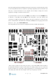
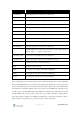
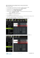
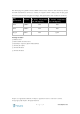
PIN & Connector
Function
I/O PWM-IN
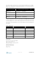
See table below for connection to Pixhawk 4
M1
I/O PWM OUT 1: connect signal wire to ESC of motor 1 here
M2
I/O PWM OUT 2: connect signal wire to ESC of motor 2 here
M3
I/O PWM OUT 3: connect signal wire to ESC of motor 3 here
M4
I/O PWM OUT 4: connect signal wire to ESC of motor 4 here
M5
I/O PWM OUT 5: connect signal wire to ESC of motor 5 here
M6
I/O PWM OUT 6: connect signal wire to ESC of motor 6 here
M7
I/O PWM OUT 7: connect signal wire to ESC of motor 7 here
M8
I/O PWM OUT 8: connect signal wire to ESC of motor 8 here
FMU PWM-IN
See table below for connection to Pixhawk 4
FMU PWM-OUT
If FMU PWM-IN is connected to Pixhawk 4, connect signal wires to
ESC or signal, +, - wires to servos here
CAP&ADC-OUT
Connect to CAP & ADC IN port of Pixhawk 4
CAP&ADC-IN
CAP & ADC input: See back of the board for pinouts
B+
Connect to ESC B+ to power the ESC
GND
Connect to ESC Ground
PWR1
5v output 3A, connect to Pixhawk 4 POWER 1
PWR2
5v output 3A, connect to Pixhawk 4 POWER 2
2~12S
Power Input, connect to 2~12S LiPo Battery
Note:Depending on your airframe type, refer to Airframe Reference to connect I/O PWM
OUT and FMU PWM OUT ports of Pixhawk 4 to PM board. MAIN outputs in PX4 firmware
map to I/O PWM OUT port of Pixhawk 4 whereas AUX outputs map to FMU PWM OUT
of Pixhawk 4. For example, MAIN1 maps to IO_CH1 pin of I/O PWM OUT and AUX1 maps
to FMU_CH1 pin of FMU PWM OUT. FMU PWM-IN of PM board is internally connected
to FMU PWM-OUT, which is used to drive servos (e.g. aileron, elevator, rudder, elevon,
gear, flaps, gimbal, steering). I/O PWM-IN of PM board is internally connected to M1-8,
which is used to drive motors (e.g. throttle in Plane, VTOL and Rover).