
Operating instructions

7Installation Instructions for Control Center VR 65
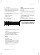
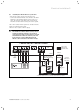
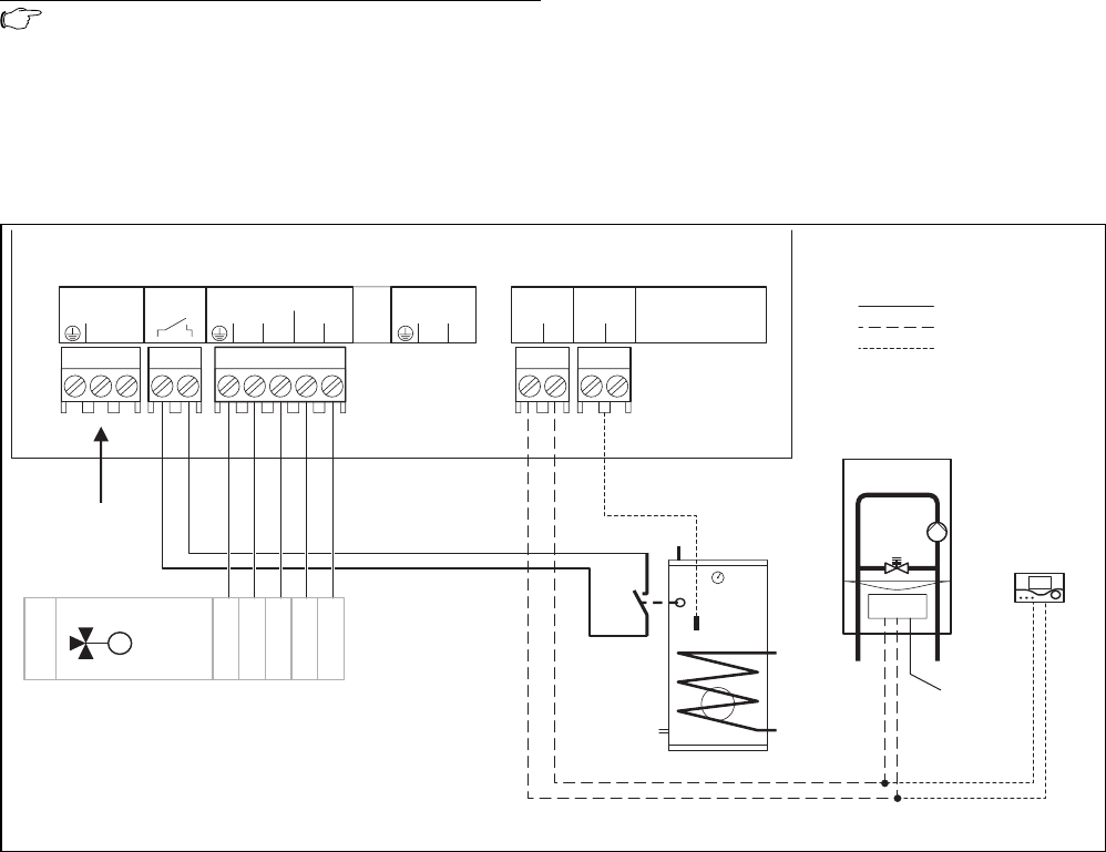
5.1 Installing the VR 65 with one 3-port valve
• Wire up the Control Center as shown in fig. 5.2.
• Connect the eBUS terminals of the VR 65 to the eBUS
terminals of the heating appliance using a two-core
cable. The polarity of the eBUS cable can be mixed.
The eBUS can be branched at any part of the system.
The Control Center VR 65 requires its own 230 V mains
supply via a switched fused spur.
The boiler also requires a 230 V supply.
Note!
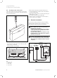
The VR 65 has a mains switch (see fig. 4.2) to
isolate the internal electronics as well as all
connected zone valves for the purposes of tests
and maintenance. When the housing cover has
been removed, a green LED indicates if the
VR 65 is still connected to the mains voltage.
CYL.
USE
DO NOT
230 V~
NL
M
3-Port
EARTH
BLUE
BROWN or
WHITE
ORANGE
GREY
DHW
onN
CH DHW
Non onoff
BUS
+-
21
NTC
* NTC (for use with
Vaillant uniSTOR only)
* Cylinder
thermostat
* Note: With Vaillant uniSTOR - use either the cylinder thermostat or the NTC
optional
(VRT 360 or
VRC 400)
VR 65
Vaillant
ecoTEC
230 V wires
eBUS (24 V)
optional (24 V)
230 V~
230 V~
Connection of Control Center
Fig. 5.2 Connection with 3-port valve
Electrical installation 5