For the qualified engineer Installation instructions Control Center VR 65 Control Center for storage connection (eBUS) GB VR 65
Contents Notes on the documentation 1 Description of the appliance 2 Contents 1 Notes on the documentation 1 Notes on the documentation . . . . . . . . . . . . . 3 2 2.1 2.2 2.3 Description of the appliance. . . . . . . . . . . . . . Data badge . . . . . . . . . . . . . . . . . . . . . . . . . . . . . . . . CE label/conformity . . . . . . . . . . . . . . . . . . . . . . . . . Intended use . . . . . . . . . . . . . . . . . . . . . . . . . . . . . . .
2 Description of the appliance 3 Safety instructions and regulations The following components can be connected - 230 V 3-port mid-position valve - 230 V cylinder thermostat or alternatively - 2 x 230 V 2-port zone valves - 230 V cylinder thermostat When Vaillant uniSTOR cylinder is installed, the NTC sensor VR 10 supplied with the VR 65 can be used instead of the 230 V cylinder thermostat.
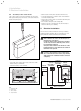
Installation 4 4 Installation The Control Center can be wall-mounted near to the DHW cylinder. The hot water and heating programs as well as all required parameters are set at the VRT 360 or VRC 400. All heating circuit connections are made at the Control Center using a ProE plug. 4.1 Installation overview Please check the following before installing the VR 65 Control Center: - Read the installation instructions - Check the scope of delivery - Assemble the VR 65 - Carry out electrical installation 4.
4 Installation 5 Electrical installation 4.4 Assembling Control Center VR 65 The Control Centre connection terminals are provided with System ProE plugs. All onsite connections must be made using these plugs. • Mark out the 2 fixing holes (2) and drill the holes. • Select the wall plugs to suit the state of the wall and screw the housing tight. • Wire up the Control Center as shown in the wiring diagrams (fig. 5.2 or 5.3). • Fix all cables using the cable clamps (3).
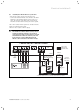
Electrical installation 5 5.1 Installing the VR 65 with one 3-port valve • Wire up the Control Center as shown in fig. 5.2. • Connect the eBUS terminals of the VR 65 to the eBUS terminals of the heating appliance using a two-core cable. The polarity of the eBUS cable can be mixed. The eBUS can be branched at any part of the system. The Control Center VR 65 requires its own 230 V mains supply via a switched fused spur. The boiler also requires a 230 V supply. Note! The VR 65 has a mains switch (see fig. 4.
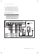
5 Electrical installation 5.2 Installing the VR 65 with two 2-port valves • Wire up the Control Center as shown in fig. 5.3. • Connect the eBUS terminals of the VR 65 to the eBUS terminals of the heating appliance using a two-core cable. The polarity of the eBUS cable can be mixed. The eBUS can be branched at any part of the system. The Control Center VR 65 requires its own 230 V mains supply via a switched fused spur. The boiler also requires a 230 V supply. Note! The VR 65 has a mains switch (see fig. 4.
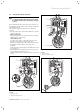
Electrical installation 5 5.3 Installing the VR 65 with a NTC Note! To comply with the approvals, the boiler must be Vaillant ecoTEC if the cylinder NTC solution is used. Before installing the NTC, first remove the cylinder control with two capillary tubes for the cylinder thermostat and thermal cut out. The cylinder control is be fitted in one of two ways (A or B). • Disconnect the wires (1) from the terminal block of the cylinder control (a). • Version A, fig. 5.
6 Start-up 7 Troubleshooting 6 Start-up The initial start-up of the VR 65 is carried out together with the initial start-up of the heating appliance. The following settings are possible: Meaning 0 Warm water priority - The 3-port valve is in the heating or hot water position depending on the operating mode. - With 2-port valves, either the DHW valve or the CH valve is open, both valves are closed on standby. Note! In the factory settings, the heating appliance operation is set to warm water priority.
Factory customer service 8 Technical data 9 8 Factory customer service To ensure regular servicing, it is strongly recommended that arrangements are made for a Maintenance Agreement. Please contact Vaillant Service Solutions (0870 6060 777) for further details. 9 Technical data Feature Unit VR 65 Operating voltage V 230 Power consumption VA 2 Contact load of output relays (max.) cos ϕ > 0.
00 2000 7476_02 GB 11 2005