
Technical data


8 Installation procedure
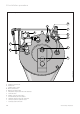
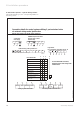
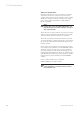
8.4.3 Control options – system wiring scheme
Important 1-10 must go to the corresponding number in
the wiring centre.
Vaillant Vantage 120/150/20026
Fig. 14
Connection details for control systems utilising 3 port motorised valve
via external wiring centre/junction box
Diagram only applies to the specific controls mentioned
LN
LN
345
3 amp fused
main supply
THERMOcompact 600 series
ECOmax 600/2 series
terminal strip
LN
LN
345
ENL
CENTRAL
HEATING
ON
HOT
WATER
ON
HOT
WATER
OFF
Programmer
for programmer connections see fig. 15
E53678
External wiring centre/junction box*
345678910
N
N
L
L
*Do not use pre-wired printed circuit board type
not used
EARTH BLUE
BROWN
OR
WHITE
GREY ORANGE
3 Port mid position motorised valve
4E5 89
543
N
4
N
4
2
4
4
3
3
3
3
2
3
3
2
1
1
L
1
L
1
1
1
1
3
E
E
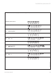
Vaillant VRT 30
ACL Drayton Digistat 1
ACL Drayton RTS 1, 2
Danfoss Randall RMT 230
Danfoss Randall RET 230
Grässlin Towerchron RS
Honeywell T6360
Horstmann HRT 2
Siemens-Landys & Staefa RAD 1
Sunvic TLX 2000 series
5 9 6 E
Room thermostat
NHTL
Potterton PRT2
BLACK BLUE BROWN EARTH
Vantage cylinder thermostat
847
E
If a room thermostat is not used,
terminals 6 and 9 of the wiring centre
must be linked
Anschluss VIH Vantage 1