Operating instructions For the operator Operating instructions ecoTEC plus Gas-fired wall-hung high efficiency boiler GB
Table of contents Table of contents 1 1.1 1.2 1.3 1.4 1.5 Notes on the documentation ................................ 3 Document storage ...................................................... 3 Symbols used ............................................................... 3 Applicability of the instructions .............................. 3 Identification plate ..................................................... 3 CE label ......................................................................... 3 2 2.
Notes on the documentation 1 1 Notes on the documentation The following instructions are intended to guide you throughout the entire documentation. Other documents apply in addition to these operating instructions. We accept no liability for any damage caused by failure to observe these instructions. Other applicable documents When operating the ecoTEC plus, you must observe all operating instructions that are included with other components of your system.
2 Safety 2 Safety 2.1 2.2 Safety and warning information > When operating your boiler, take account of the general safety instructions and the warning notes that appear before each action. 2.1.
Safety 2 2.3 General safety instructions > Observe the following safety instructions at all times. What to do in an emergency if you smell gas Installation errors, damage, handling, unauthorised installation sites or similar can cause gas to escape and result in a risk of poisoning and explosion. If there is a smell of gas in the building, proceed as follows: > Avoid rooms that smell of gas. > Open all accessible doors and windows fully and ensure adequate ventilation. > Avoid the use of naked flames (e.
2 Safety Preventing frost damage If there is a power cut, or if the room temperature is set too low in individual rooms, it cannot be ruled out that sections of the heating system might be damaged by frost. > If you are going to be away during a cold period, make sure the heating system remains in operation and that the rooms are sufficiently heated. > Always observe the information on frost protection provided in section 4.9.
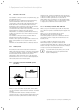
Equipment and functional description 3 3 Equipment and functional description 3.1 Design 16 14 1 1 2 2 3 15 13 4 4 5 5 6 7 14 3 6 12 7 8 8 9 9 13 11 12 10 11 Fig. 3.
3 Equipment and functional description 3.2 Function of the boiler Your Vaillant ecoTEC plus boiler is a high-efficiency, gasfired wall-hung boiler. In addition to direct combustion heat, high-efficiency gas-fired wall-hung boilers also use the heat of condensation of the steam in the exhaust fumes. This makes them more efficient than traditional boilers.
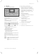
Operation 4 4 Operation 4.1 The control elements are explained below. Overview of control elements 1 Display for showing the current heating flow temperature, the fill pressure of the heating system, the operating mode or other information 2 "Operating mode" selection button to choose and call up information, e.g.
4 Operation 4.2 Display Hot water production active Digital Information and Analysis System (DIA) On VUW/APC units: flashing: Burner on in draw-off mode 9 10 11 Fig. 4.2 Display ecoTEC plus The ecoTEC plus boiler is fitted with a digital information and analysis system (DIA). This system provides information on the operating status of your boiler and helps you deal with problems.
Operation 4 4.3 Preparing for start-up 4.3.2 4.3.1 Opening the isolator devices b i The isolator devices are not included in the scope of supply of your boiler. The isolator devices are fitted by your heating engineer on site. > He must explain to you the position and handling of these components. Switching on the boiler Caution! Material damage caused by frost! Frost protection and monitoring devices are only active while the boiler is connected up to the power supply.
4 Operation 4.3.3 Checking the fill level of the heating system b Caution! Low fill pressure can cause damage to the unit! Operating the heating system with low fill pressure can cause damage to the boiler and the heating system. The boiler switches off automatically when the fill pressure falls below 0.5 bar. > Fill up the heating system as soon as the fill pressure falls below 0.8 bar.
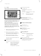
Operation 4 1 Water pressure 3 1,2bar min. 0,5 4.4 Setting the heating flow temperature 4.4.1 Setting the heating flow temperature without a controller connected 2 max. 3,0 Target flow temp. Back 58 °C 1/4 Cancel Ok Fig. 4.5 Display Fill pressure You can show the exact fill pressure in the display. > Press the "Menu" selection button . A selection of menu options appears in the display. Fig. 4.
4 Operation 4.4.2 Setting the heating flow temperature with a controller If your gas-fired wall-hung boiler has a room thermostat control system or weather compensator, make the following settings: The flow temperature is automatically adjusted by the controller (for information see the controller operating instructions). Hot water production with VUW units 4.5.1 Setting the hot water temperature a a b The hot water temperature is shown on the display.
Operation 4 Activate comfort mode by pressing the following sequence of keys: "Operating mode" selection button --> "Next" --> "Next" "Comfort mode off" is shown on the display. > Change "Comfort mode off" to "Comfort mode on" using the "Scroll down" or "Scroll up" arrow keys. > Confirm the change by pressing the "OK" selection . button Comfort mode is now set. > Press the "Next" or "Back" selection button until you have reached the desired level or the basic display. Fig. 4.
4 Operation 4.5.3 Setting storage tank charging (with actoSTOR) Switching on cylinder charging In an additional stratified storage tank of the type actoSTOR VIH CL 20 S is connected you can switch cylinder charging on and off using the controller on your gas-fired wall-hung boiler. Cylinder charging refers to the process for heating up the cylinder. > Press the on/off switch to switch on the boiler.
Operation 4 4.6 Hot water production with VU units 4.6.1 Setting the hot water temperature a a b Danger! Risk of being scalded by hot water! There is a danger of scalding at the hot water draw-off points if the temperatures are greater than 60 °C. Young children and elderly persons can be at risk at lower temperatures. > Select the temperature so that nobody is at risk. Danger! Possible danger to life from legionella formation.
4 Operation 4.8 Switching the heating system off 4.8.3 Temporarily taking the boiler out of service 4.8.1 Switching hot water production off (VU unit) b You can switch off cylinder charging without switching off heating mode. > Set the lowest possible hot water temperature by pressing the following sequence of keys: "Operating mode" selection button --> "Next" The hot water temperature is shown on the display.
Operation 4 4.9 Protecting the heating system against frost b Caution! Material damage caused by frost! Frost protection and monitoring devices are only active while the boiler is connected up to the power mains and the on/off switch is on. > Do not isolate the boiler from the power mains. > Leave your boiler switched on at the on/off switch.
5 Energy saving tips 5 Energy saving tips Installation of a weather compensator Weather compensators regulate the heating flow temperature with reference to the outside temperature. No more heat is generated than is currently required. The designated heating flow temperature for the corresponding outside temperature must be set on the weather compensator. This setting must not be greater than that required by the design of the heating system.
Energy saving tips 5 the extent that is necessary for use. Any further heating results in unnecessary power consumption and hot water temperatures of more than 60 °C also lead to increased lime scale reduction. Switching on comfort mode (only VUW): Comfort mode immediately supplies you with hot water at the required temperature, without you having to wait for the water to heat up. For this, the hot water heat exchanger is kept at a preselected temperature level.
6 Troubleshooting 6 Troubleshooting a Display Danger! Danger of injury and material damage due to incorrect maintenance and repairs! If maintenance is not carried out, or carried out incorrectly, this may adversely affect the operating reliability of your boiler. > Never attempt to perform maintenance or repairs on your boiler by yourself. > Always employ an approved heating engineer.
Troubleshooting 6 6.1 Reading fault codes If a fault develops in the boiler, the display shows a fault code starting with "F...". A plain text display explains the displayed fault code. Example for F.10: "Short circuit heating feed sensor". Fault codes have priority over all other displays. If a fault occurs, then the display no longer shows the current heating flow temperature.
Troubleshooting 6 6.3 Rectifying a water shortage b Caution! Tap water that is extremely calciferous or corrosive or contaminated by chemicals can cause material damage! Unsuitable tap water damages the seals and diaphragms, blocks components in the boiler and heating system through which the water flows and causes noise. > Only fill the heating system with suitable tap water. > In case of doubt, consult your approved heating engineer. 6.
Troubleshooting 6 Maintenance 7 6.5 Resolving faults in the air/exhaust gas pipework a Danger! Risk of injury and material damage resulting from improper modifications! Improper alterations can affect the operating safety of your boiler. > Never attempt to perform repairs on your boiler by yourself. > Always employ a recognised heating engineer. The boilers are fitted with a blower. If the blower does not work properly, the boiler will switch itself off. The error message "F.32" appears in the display.
8 Decommissioning 9 Manufacturer's guarantee and Vaillant customer service 8 8.1 Decommissioning Disconnecting the boiler permanently > Contact a heating engineer to disconnect the boiler permanently. 8.1.1 Disposing of the boiler Do not dispose of your Vaillant ecoTEC plus boiler or any of its accessories in the household waste. > Make sure the old unit and any accessories are disposed of properly. > Observe national regulations. 8.1.
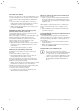
10 Technical data 10 Technical data ecoTEC plus Nominal heat output range P at 40/30 °C Nominal heat output range P at 50/30 °C Nominal heat output range P at 60/40 °C Nominal heat output range P at 80/60 °C Hot water output Maximum thermal load for heating drinking water Maximum thermal load on heating-side Minimum thermal load Heating output setting range Heating max. flow temperature Setting range max.
10 Technical data ecoTEC plus Unit Electric connection V/Hz VU GB 126/5-5 VU GB 156/5-5 VU GB 186/5-5 VU GB 246/5-5 VU GB 306/5-5 VU GB 376/5-5 230/50 Built-in fuse 2 A, slow-blow Minimum electrical power consumption W 40 40 45 50 50 50 Maximum electrical power consumption W 90 90 90 95 95 110 type of protection IP X4 D Quality mark/certification number Tab. 16.
Technical data 10 ecoTEC plus Nominal heat output range P at 40/30 °C Nominal heat output range P at 50/30 °C Nominal heat output range P at 60/40 °C Nominal heat output range P at 80/60 °C Hot water output Maximum thermal load for heating drinking water Maximum thermal load on heating-side Minimum thermal load Heating output setting range Heating max. flow temperature Setting range max.
10 Technical data ecoTEC plus Unit Electric connection V/Hz VUW GB 246/5-5 VUW GB 316/5-5 VUW GB 376/5-5 VUI GB 376/5-5 230/50 Built-in fuse 2 A, slow-blow Minimum electrical power consumption W 45 50 50 50 Maximum electrical power consumption W 90 95 110 110 type of protection IP X4 D Quality mark/certification number Tab. 16.
Operating instructions ecoTEC plus 0020124810_FT1b 31
Glossary Glossary Air/exhaust gas pipework The air/exhaust gas pipework consists of all components that route combustion air to the boiler or exhaust gas from the boiler. Burner The burner on a condensing boiler is the component in which the gas/air mix is control-burnt. Calorific value Unlike the heating value, the calorific value of a fuel describes the total useable heat during combustion, based on the quantity of fuel used, including the condensation heat in the steam.
Glossary Room thermostat A room thermostat continuously measures the room temperature and compares it with the room temperature you have set (target room temperature). This allows the heating system to maintain a constant set temperature in your room. In addition, you can enter individual heating times. The target room temperature and the heating times set by you control the operation of your boiler, the power of which is adapted automatically to the respective heat demand.
Index Index A Air/exhaust gas pipework ........................................ 4, 25, 32 L Legionella protection function ........................................... 16 B Burner blocking time ............................................................ 10 M Malfunction ............................................................... 23, 24, 25 Must be reported .................................................................. 22 C CE label ...............................................................
Manufacturer 0020124810_FT1b GB 022011 – Subject to alterations Supplier