
Technical data


39
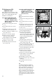
7.10 Replacement of
transformer
•
Isolate boiler from the electricity
supply.
•
Remove front casing as in section
7.1.3
•
Lower front control panel as in
section 7.1.6.
•
Disconnect ignition leads (3, fig.
65) from rear of control box.
•
Remove back of control box by
undoing the 3 screws (1 and 2, fig.
65).
•
Unplug transformer (A, fig 67)
connecting lead from main switch
board.
Move clips (3, fig. 67) to the left
and remove transformer from
control box.
•
Reassemble in reverse order.
•
Carry out electrical checks (see
section 5.1).
7.11 Replacement of overheat
thermostat
•
Isolate the boiler from the electricity
supply.
•
Remove front casing as in section
7.1.3.
•
Lower front panel as in section
7.1.6.
•
Pull wires off overheat thermostat
(2, fig 66).
•
Unscrew overheat thermostat to
remove.
•
Reassemble in reverse order.
•
Carry out electrical checks (see
section 5.1).
7.12 Replacement of pump
•
Remove front casing as in section
7.1.3.
•
Turn boiler off as in section 7.1.1.
•
Release pressure and drain boiler
as in section 7.1.2.
•
Lower front control panel as in
section 7.1.6.
•
Disconnect ignition leads (3, fig.
65) from rear of control box.
•
Remove back of control box by
undoing the 3 screws (1 and 2,
fig. 65).
•
Unplug pump wire from main
switchboard, and remove earth
lead from earth strip.
•
Undo the 3 pump screws (1, fig.
68).
13
2
fig. 65
GW 614/1
2
1
3
fig. 66
GW 645/0
N
L
3
4
5
7
8
9
1
2
3
A
fig. 67
GW 615/2X
2
1
3
fig. 68
GW 559/1
•
Pull pump forward to remove.
•
Fit new '0' rings (supplied with
pump) to pump connections.
•
Re-assemble in reverse order.
•
Carry out electrical checks
(see section 5.1).