
Technical data


3 Boiler Specification
Instructions for Installation and Servicing turboMAX pro R36
3.3 Functional Diagram
Fig. 3.2: Functional Diagram
1 Air duct
2Fan
3 Main heat exchanger
4 Temperature sensor (NTC I)
5 Flame sensing electrodes
6 Modulating burner
7 Fully modulating automatic gas value
8 Maximum hot water temperature control
9 Maximum radiator temperature control
10 Diverter valve
11 DHW heat exchanger
12 Automatic bypass valve
13 CH flow service valve
14 Hot water outlet
15 Gas service valve
16 Cold water service valve
17 CH return service valve
18 Pressure relief valve
19 Aqua sensor (DHW flow switch)
21 Main on/off control
22 Pressure gauge
23 Indicator lights
24 Expansion vessel
25 Expansion vessel charging valve
26 Circulating pump
27 Automatic air vent
28 Ignition electrode
29 Temperature sensor (NTC II)
30 Air pressure switch
31 Flue gas duct
C
C
1
2
3
4
5
6
7
8
9
10
11
12
13
14
15
17
16
18
19
21
22
23
24
25
26
27
28
29
30
31
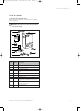
3.2 Boiler connections
Fig. 3.1: Connection diameters turboMAX pro
Key:
1 Heating system return (22 mm tail)
2 Cold water connection with shut off valve
(15 mm tail)
3 Gas connection (15 mm tail)
4 Hot water connection (15 mm tail)
5 Heating system flow (22 mm tail)
6 Flue outlet (100 mm flue with turret)
7 Hanging bracket
8 Rear flue outlet
0
7
6
264638
145
6
5
100
100
35 35
432
130
180
1
148
8
543 2 1
902
833792_41GB_012005.qxd 09.03.2005 16:47 Uhr Seite 6