
Technical data


Functional Checks (Commissioning Part III) 8
Instructions for Installation and Servicing turboMAX pro R3 25
8 Functional Checks
8.1 Functional checks
Procedure
Once the unit has been installed and the gas supply has
been checked, operate the system to ensure that it is
working correctly.
• Operate the system, following the operating instruc-
tions supplied with the boiler.
• Check the system for water leaks and escaping gas.
• Check that the flue has been correctly installed,
according to the fitting instructions supplied with the
flue assembly.
• Check the burner for correct ignition and flame
picture.
• Check the hot water system for correct operation.
• Check the heating system for correct operation.
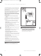
Fig. 8.1 Test for correct functioning
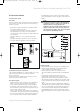
8.2 Functional check of operation
The Vaillant turboMAX pro is equipped with a set of dia-
gnostic indicator lights to show the operational
status of the boiler.
A functional check of DHW and CH operation can be
made using these indicator lights.
Hot water system
• Ensure that the power on indicator (1) is illuminated.
• Turn on a hot top and draw water at a high rate.
• The hot water demand indicator (2) will illuminate.
• The appliance will start its lighting sequence. Once
the fan and flue system has proved itself, the fan ope-
ration indicator (4) will light.
• The gas valve will open and sparking will commence
at the burner. The ignition indicator (5) will illuminate.
• As soon as the burner has ignited and the flame has
been sensed the flame indicator (6) will illuminate.
I
0
• By illuminating in this sequence the indicator lights
have demonstrated correct operation of the boiler for
DHW.
Note!
Should the boiler fail to light it will attempt 2
re-ignition sequences, if the boiler still fails to
light the burner lock out indicator will
illuminate (7). This usually means that the gas
supply is turned off or has not been purged of
air. Check the gas supply, push the reset button
and repeat the lightning procedure.
Fig. 8.2 Functional check
Heating system
• Ensure that the power on indicator is illuminated (1).
• Ensure that the maximum radiator temperature
control is turned to the high position.
• Ensure external controls are calling for heat.
• The central heating demand indicator will illuminate
(3).
• Providing the boiler has not achieved its set
temperature, and the anti-cycling control is not
activated, the boiler will start its lighting sequence.
Once the fan and flue system have proved their satis-
factory operation the fan operation indicator (4) will
light.
• The gas valve will open and sparking will commence
at the burner. The ignition indicator (5) will illuminate.
• As soon as the burner has ignited and the flame has
been sensed the flame indicator (6) will illuminate.
• By illuminating in this sequence the indicator lights
have demonstrated correct operation of the boiler for
CH.
I
0
1
2
3
4
5
67
833792_41GB_012005.qxd 09.03.2005 16:47 Uhr Seite 25