
Technical data

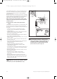


Gas supply adjustments (Commissioning Part II) 7
Instructions for Installation and Servicing turboMAX pro R3 23
Burner Pressure turboMAX pro 24/2 E
Delivered gas Output[kW] Ignition rate 8.9 10.0 12.0 14.0 16.0 18.0 20.0 22.0 24.0
Natural gas 2H Burner pressure
1)
[mbar]
Main burner jet mark
2)
for G20
1.9 1.9 2.1 2.9 3.7 4.7 5.8 6.7 8.4 9.8
7 / 120
LPG 3+
Burner pressure
1)
[mbar]
Main burner jet mark
2)
for G30 3.9 3.9 4.9 6.9 9.2 11.8 14.7 17.8 21.1 24.7
7 / 072 for G31 5.4 5.4 6.7 9.4 12.5 16.0 19.8 24.0 28.5 33.3
Burner Pressure turboMAX pro 28/2 E
Delivered gas Output[kW] Ignition rate 10.4 12.0 14.0 16.0 18.0 20.0 22.0 24.0 26.0 28.0
Natural gas 2H Burner pressure
1)
[mbar]
Main burner jet mark
2)
for G20
1.8 1.8 2.3 3.0 3.9 4.8 5.8 6.8 8.0 9.2 10.5
7 / 120
LPG 3+
Burner pressure
1)
[mbar]
Main burner jet mark
2)
for G30 3.8 3.8 5.0 6.7 8.7 10.8 13.1 15.6 18.3 21.2 24.2
7 / 072 for G31 5.3 5.3 6.9 9.3 11.9 14.8 18.0 21.4 25.1 29.0 33.1
Gas Rate turboMAX pro 24/2 E
Delivered gas Output[kW] 8.9 10.0 12.0 14.0 16.0 18.0 20.0 22.0 24.0
Natural gas 2H Gas Rate
1)
[m
3
/h]
Main burner jet mark
2)
for G20
1.1 1.2 1.4 1.7 1.9 2.1 2.4 2.6 2.8
7 / 120
Gas Rate turboMAX pro 28/2 E
Delivered gas Output[kW] 10.4 12.0 14.0 16.0 18.0 20.0 22.0 24.0 26.0 28.0
Natural gas 2H Gas Rate
1)
[m
3
/h]
Main burner jet mark
2)
per G20
1.3 1.5 1.7 1.9 2.1 2.4 2.6 2.8 3.1 3.3
7 / 120
7.4 Burner Pressure and gas rate
Table 7.1 Burner pressure
1) 15 °C, 1013mbar, dry
2) The nozzles are stamped with the mark shown in this table.
The marking corresponds to the nozzle hole diameter multiplied by 100
Table 7.2 Gas flow rate
1) 15 °C, 1013mbar, dry
2) The nozzles are stamped with the mark shown in this table.
The marking corresponds to the nozzle hole diameter multiplied by 100
833792_41GB_012005.qxd 09.03.2005 16:47 Uhr Seite 23