
Technical data


Boiler Installation Sequence 5
Instructions for Installation and Servicing turboMAX pro R3 17
Abb. 0.0 Bildunterschrift
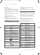
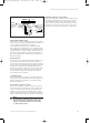
Fig. 5.11 Connection wiring
NL987
F3
543
24V
230V
F1
5.13 Electronic board layout
Socket X2 for internal unit components
Socket X4 for minority reversing
Socket X7 for accessory box connection
Socket X8 for VRC-VC connection
Room thermostat, 230 V: connections 3, 4 and 5
Mains power supply: connections L, N and earth
Socket X12: pump connection
Socket X14: gas valve connection
Socket X13: fan unit connection
Do not
use!
833792_41GB_012005.qxd 09.03.2005 16:47 Uhr Seite 17