
Technical data


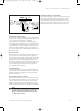


5.7 Gas supply
• Connect the 15 mm compression gas service cock (1)
supplied with the appliance (2) and tighten.
• Connect a gas supply pipe of not less than 15 mm
diameter to the gas service cock.
• Tighten all connections.
(Ensure the gas supply pipework is adequately sized
such that a 20 mbar gas pressure is available at the
boiler inlet at full flow rate).
Fig. 5.6: Fitting the gas connection
I
0
1
2
5 Boiler Installation Sequence
Instructions for Installation and Servicing turboMAX pro R314
5.4 Install the flue system
Install the flue system (refer to separate air/flue duct
installation instructions).
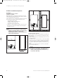
5.5 Fitting the boiler
• Lift the boiler (3) up to the wall so that it is slightly
above the hanging bracket (1).
Note!
Lift the boiler from either side at the bottom
edge.
• Lower the boiler slowly onto the hanging bracket so
that the cross member at the rear of the boiler fully
engages onto the hanging bracket.
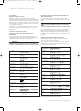
5.6 Removing boiler casing
• Turn both securing fasteners (1) anti-clockwise by 90°
to release control panel (2).
• Pull the case (3) forward at the bottom to disengage
from the securing clips.
• Lift the case slightly to clear the top locations and pull
forward to remove.
Fig. 5.5: Remove of boiler casing
3
I
0
2
I
0
90°90°
1
833792_41GB_012005.qxd 09.03.2005 16:47 Uhr Seite 14