
Technical data


4 General Requirements
Instructions for Installation and Servicing turboMAX pro R310
Important!
This appliance must be earthed.
4.8 Guide to system requirements
4.8.1 Water circulation system
Detailed recommendations for the water circulation
system are given in BS 6798 and BS 5449: Part 1 (for
small bore and micro bore central heating systems).
Pipework not forming part of the useful heating surface
should be insulated to help prevent heat loss and
possible freezing, particularly where pipes are run
through roof spaces and ventilated underfloor spaces.
Draining taps must be located in accessible positions
which permit the draining of the whole system including
the boiler and the hot water system. Draining taps
should be at least 1/2 in. BSP nominal size and be in
accordance with BS 2879.
The boiler is suitable for use with minibore or microbore
systems. Copper tubing to BS 2871: Part 1 should be
used for water carrying pipework. All capillary joints in
all DHW pipework must be made with lead free solder.
Particularly where a new boiler is to be fitted to an
existing system, it is good practice that the system is
thoroughly cleansed.
Important:
To prevent the formation of deposits and pre-
vent serious damage to the appliance and
system , cleansers must be used carefully and
must be completely removed by thoroughly
flushing the system. Cleansers should only be
left in systems for a maximum of 24 hours.
This cleansing must take place prior to the fitting of the
new boiler and be in accordance with BS 7593.
For advice on the application of system cleansers
contact either Sentinel, GE Betz. Widnes, Cheshire,
WA8 8UD. Tel: 0151 420 9595
4.8.2 Filling and make up
The system can be filled using the built in filling loop.
The connection must be removed when filling is
completed. Where local Water Authority regulation does
not allow temporary connection, a sealed system filler
pump with break tank must be used. The heating system
will not be filled automatically from the domestic hot
water side.
(Alternative methods of filling sealed systems are given
in BS 5449).
4.8.3 Pressure relief valve
A pressure relief valve is provided with the boiler. This
safety device is required on all sealed C.H. systems and
is preset at 3 bar and provided with a 15 mm
compression connection for a discharge pipe, which
must be of no less than 15 mm in diameter. The
Pressure Relief Valve must not be used for draining
purposes.
4.8.4 Pressure gauge
This is factory fitted to the boiler and indicates the
primary circuit pressure to facilitate filling and
testing.
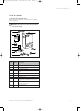
4.8.5 Expansion vessel
The 24 kW boiler incorporate a 6 litre expansion vessel
which is suitable for a sealed heating system with a
maximum water content of 60 litres. A 10 litre
expansion vessel kit is available as an optional
accessory.
The 28 kW boilers incorporate a 10 litre expansion
vessel which is suitable for a sealed heating system with
a maximum water content of 100 litres. If the nominal
capacity of the built in expansion vessel is not sufficient
for the heating system (for instance in case of moder-
nization of old open systems) an additional expansion
vessel can be installed external to the boiler. It should
be fitted in the return pipe as close as possible to the
boiler in accordance with BS 5449: Part 1. Guidance on
the sizing of an additional expansion vessel is given in
Table.
Vessel Volume [L]
Initial system pressure (bar) 1.0 1.5
Pressure relief valve setting (bar) 3.0
Total water content of system ltres
25 2.7 3.9
50 5.4 7.8
100 10.9 15.6
125 13.6 19.5
150 16.3 23.4
175 19.1 27.3
200 21.8 31.2
225 24.5 35.1
250 27.2 39.0
275 30.0 42.9
300 32.7 46.8
325 35.7 50.7
350 38.1 54.6
375 40.9 58.5
400 43.6 62.4
425 46.3 62.4
450 49.0 58.5
475 51.8 74.1
500 54.5 78.0
For system volumes other than those given
above, multiply the system volume by the
factor across 0.109 0.156
833792_41GB_012005.qxd 09.03.2005 16:47 Uhr Seite 10