833792_41GB_012005.qxd 09.03.
833792_41GB_012005.qxd 09.03.2005 16:47 Uhr Seite 2 Table of Contents 1 1.1 List of Contents . . . . . . . . . . . . . . . . . . . . . Contents included with boiler (turboMAX pro)3 3 2 2.1 2.2 Introduction . . . . . . . . . . . . . . . . . . . . . . . . General Information . . . . . . . . . . . . . . . . . . . . . EC designation . . . . . . . . . . . . . . . . . . . . . . . . . . 4 4 4 3 3.1 3.2 3.3 Boiler Specification . . . . . . . . . . . . . . . . . . . Technical data . . . . . . . . . . . .
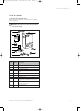
833792_41GB_012005.qxd 09.03.2005 16:47 Uhr Seite 3 List of contents 1 1 List of contents 1.1 Contents included with boiler Ensure that all contents are included before commencing installation. Note! DO NOT remove the boiler from the polystrene base at this stage. 10 1 9 8 I 7 0 2 6 5 3 4 Fig. 1.
833792_41GB_012005.qxd 09.03.2005 16:47 Uhr Seite 4 2 Introduction 2 Introduction 2.1 General Information Note! This boiler must be installed and serviced by a competent person in accordance with the Gas Safety (Installation and Use) Regulations 1998. In the UK „CORGI“ registered installers undertake the work to a safe and satisfactory standard. The turboMAX pro is a fully automatic, wall mounted, room sealed combination boiler for central heating and domestic hot water.
833792_41GB_012005.qxd 09.03.2005 16:47 Uhr Seite 5 Boiler Specification 3 3 Boiler Specification 3.1 Technical Data Maximum CH heat input (net) CH heat output range (80/60 °C) turboMAX pro 24/2 E (VUW GB 242/2-3) turboMAX pro 28/2 E (VUW GB 282/2-3) 29.7 (101.000) 31.1 (106.200) Units kW (Btu/h) 8.9 - 24 10.4 - 28 (30.400 - 81.900) (35.500 - 95.500) kW (Btu/h) Maximum DHW heat input (net) 26.7 (91.200) 31.1 (106.200) kW (Btu/h) SEDBUK Band D D SAP Seasonal Efficiency 79.6 79.
833792_41GB_012005.qxd 09.03.2005 16:47 Uhr Seite 6 3 Boiler Specification 3.2 Boiler connections 3.3 Functional Diagram 1 31 264 6 8 2 145 148 30 29 3 902 7 4 638 5 6 28 6 27 5 4 3 2 7 1 26 25 0 130 35 180 8 35 9 100 C 24 23 C 22 21 100 10 5 4 Fig. 3.
833792_41GB_012005.qxd 09.03.2005 16:47 Uhr Seite 7 General Requirements 4 4 General Requirements 4.1 Related Documents The installation of the boiler must be in accordance with the relevant requirements of Gas Safety (Installation and Use) Regulations 1998, Health and Safety Document No. 635 (The Electricity at Work Regulations 1989), BS7671 (IEE Wiring Regulations) and the Water Supply (WaterFittings) Regulations.
33792_41GB_012005.qxd 09.03.2005 16:47 Uhr Seite 8 4 General Requirements 4.4.1 Top outlet flue system (100 mm outside diameter) The top outlet horizontal flue system (Art. No. 303 807) is suitable for installations up to 720 mm measured from the centre of the boiler flue outlet to the outside face of the wall. Flue extensions are available to extend this length up to 4.5 m for 24 kW and 3.2 m for 28 kW. Both 90° bends and 45° elbows are also available to increase siting flexibility.
833792_41GB_012005.qxd 09.03.2005 16:47 Uhr Seite 9 General Requirements 4 4.4.4 Flue termination The following details refer to both flue systems. a. The terminal must be positioned such that the products of combustion can disperse freely at all times. b. In certain weather conditions a plume of water vapour may be visible from the flue terminal. Positions where this could be a nuisance should be avoided. c.
833792_41GB_012005.qxd 09.03.2005 16:47 Uhr Seite 10 4 General Requirements Important! This appliance must be earthed. 4.8 Guide to system requirements 4.8.1 Water circulation system Detailed recommendations for the water circulation system are given in BS 6798 and BS 5449: Part 1 (for small bore and micro bore central heating systems).
833792_41GB_012005.qxd 09.03.2005 16:47 Uhr Seite 11 General Requirements 4 4.8.6 Circulating pump The circulating pump is included in the boiler. The pump head available for the heating system is shown in fig. 4.6. Lift [mbar] 700 650 600 550 500 setting III 450 400 350 300 250 setting II 200 150 100 50 0 100 200 300 400 500 600 700 800 900 1000 1100 1200 1300 1400 Volume flow [l/h] Fig. 4.6: Pump specifications 4.8.
833792_41GB_012005.qxd 09.03.2005 16:47 Uhr Seite 12 5 Boiler Installation Sequence 5 Boiler Installation Sequence 5.1 General Preparation of boiler location Clearances required Mount the boiler on a flat and vertical area of wall of sufficient area for the boiler plus the required clearances for installation and servicing.
833792_41GB_012005.qxd 09.03.2005 16:47 Uhr Seite 13 Boiler Installation Sequence 5 5.2 Using boiler template Fix the paper template to the wall ensuring that the correct flue exit point has been identified, ensure that the template is vertical. The template shows - The position of the fixing holes for the boiler mounting bracket (1). - The position of the connections. - The position of the flue exit hole. - Upper hole (2) indicates top outlet flue with flue turret facing rearward.
833792_41GB_012005.qxd 09.03.2005 16:47 Uhr Seite 14 5 Boiler Installation Sequence 5.4 Install the flue system Install the flue system (refer to separate air/flue duct installation instructions). 5.5 Fitting the boiler • Lift the boiler (3) up to the wall so that it is slightly above the hanging bracket (1). Note! Lift the boiler from either side at the bottom edge. 5.7 Gas supply • Connect the 15 mm compression gas service cock (1) supplied with the appliance (2) and tighten.
833792_41GB_012005.qxd 09.03.2005 16:47 Uhr Seite 15 Boiler Installation Sequence 5 5.8 Cold water mains inlet and hot water outlet Flush all foreign matter from the mains supply before connecting to the boiler. • Connect the cold water service valve (1) to the cold inlet water connection (3) of the appliance with the washer (2) provided and tighten. • Connect the cold water inlet pipe copper tail to the cold water service valve and tighten.
833792_41GB_012005.qxd 09.03.2005 16:47 Uhr Seite 16 5 Boiler Installation Sequence 5.10 Connect the flue system to the boiler • Refer to separate air/flue duct installation instructions included with the boiler. 3 5.11 Electrical installation General requirements Important! All electrical work shall be carried out by a competent person and shall comply with BS7671 (IEE Regulations). The boiler is supplied for connection to 230 V, ~ 50 Hz supply fused at 3 A rating.
833792_41GB_012005.qxd 09.03.2005 16:47 Uhr Seite 17 Boiler Installation Sequence 5 5.13 Electronic board layout Socket X2 for internal unit components Socket X4 for minority reversing Socket X7 for accessory box connection Socket X8 for VRC-VC connection F3 7 8 9 24V Do not use! L N Mains power supply: connections L, N and earth 3 4 5 230V Room thermostat, 230 V: connections 3, 4 and 5 Socket X12: pump connection Socket X14: gas valve connection Socket X13: fan unit connection Abb. 0.
833792_41GB_012005.qxd 09.03.2005 16:47 Uhr Seite 18 5 Boiler Installation Sequence 5.14 Controls External electrical controls The boiler terminals 3, 4 and 5 are for connecting external electrical controls such as a time switch and/or room thermostat. Terminals 3 and 4 are linked together when the boiler is supplied. If external controls are used, this link must be removed, and the controls connected across terminals 3 and 4.
833792_41GB_012005.qxd 09.03.2005 16:47 Uhr Seite 19 Boiler Installation Sequence 5 DO NOT USE IN UK! 20 VDC 7 8 9 LN MAINS SUPPLY N 230 V L 50 Hz 3 A FUSE 34 5 SWITCH CONTACTS L N CLOCK ROOM THERMOSTAT Automatic pump spin control (APS) The boiler incorporates a built in control which will spin the built in circulating pump and operate the diverter valve (turboMAX only) once in a 24 hour period. This control helps to prevent seizure when the boiler is not operated for a period of time.
833792_41GB_012005.qxd 09.03.2005 16:47 Uhr Seite 20 6 Commissioning Part I 6 Commissioning Part I 2 6.1 Preliminary electrical checks Check the electrical installation by carrying out short circuit, earth continuity and resistance to earth tests and a check for correct polarity. 6.2 Gas supply The complete gas installation including the gas meter must be inspected, tested for soundness and purged in accordance with BS 6891.
833792_41GB_012005.qxd 09.03.2005 16:47 Uhr Seite 21 Gas supply adjustments (Commissioning Part II) 7 7 Gas supply adjustments 7.1 Gas inlet working pressure To check the gas inlet working pressure: • Lower the front panel of the boiler. • Lower the control panel. • Slacken the sealing screw (1) located at measuring point ”P.IN”. • Attach U-gauge to the inlet test point on the gas valve (2). • Ensure that the gas service valve is open.
833792_41GB_012005.qxd 09.03.2005 16:47 Uhr Seite 22 7 Gas supply adjustments (Commissioning Part II) Set the DHW temperature control to maximum and fire the boiler at full rate by fully opening a hot water tap. Check that the burner pressure is as the maximum shown in table 7.1. Measure the domestic hot water mode burner operating pressure (mbar), the heat input (kW), the inlet and outlet domestic hot water temperatures (°C) and flow rate (l/min) and record details in the boiler logbook.
833792_41GB_012005.qxd 09.03.2005 16:47 Uhr Seite 23 Gas supply adjustments (Commissioning Part II) 7 7.4 Burner Pressure and gas rate Burner Pressure turboMAX pro 24/2 E Delivered gas Output[kW] Natural gas 2H Burner pressure1) [mbar] Main burner jet mark2) for G20 Ignition rate 8.9 10.0 12.0 14.0 16.0 18.0 20.0 22.0 24.0 1.9 1.9 2.1 2.9 3.7 4.7 5.8 6.7 8.4 9.8 14.7 17.8 21.1 24.7 7 / 120 LPG 3+ Burner pressure1) [mbar] Main burner jet mark2) for G30 3.9 3.9 4.9 6.9 9.
833792_41GB_012005.qxd 09.03.2005 16:47 Uhr Seite 24 7 Gas supply adjustments (Commissioning Part II) 7.5 Fit combustion chamber cover Carefully re-fit the combustion chamber cover to the boiler ensuring it is correctly sealed. Secure cover with retaining clamps. 7.6 Fit boiler casing • Carefully push case (1) onto the boiler such that the locating points either side at the top of the boiler engage. Push the casing onto the securing clips at the bottom of the boiler. • Close control panel (2).
833792_41GB_012005.qxd 09.03.2005 16:47 Uhr Seite 25 Functional Checks (Commissioning Part III) 8 8 Functional Checks 8.1 Functional checks Procedure Once the unit has been installed and the gas supply has been checked, operate the system to ensure that it is working correctly. • Operate the system, following the operating instructions supplied with the boiler. • Check the system for water leaks and escaping gas.
833792_41GB_012005.qxd 09.03.2005 16:47 Uhr Seite 26 8 Functional Checks (Commissioning Part III) 8.3 Adjusting pump speed The unit is fitted with a two-speed pump. The pump is delivered with the switch (1) set to position III.
833792_41GB_012005.qxd 09.03.2005 16:47 Uhr Seite 27 Servicing 9 9 Servicing 9.1 Initial Inspection To ensure the continued safe and efficient operation of the boiler it is recommended that it is checked and serviced as necessary at regular intervals. The frequency of servicing will depend upon the particular installation conditions and usage, but in general once per year should be adequate. It is the law that all servicing work is carried out by a competent person (Corgi registered).
833792_41GB_012005.qxd 09.03.2005 16:47 Uhr Seite 28 9 Servicing 9.2 Cleaning the burner and primary heat exchanger • Turn off the boiler. • Isolate the electrical supply to the boiler. • Remove the boiler case as described. • Turn off the gas service valve. • Turn off the boiler CH service valves. • Turn off the cold water inlet service valve. • Release the three clamps (1), remove the combustion chamber cover (2). • Pull the three cables (4) and two tubes (5) from the fan assembly.
833792_41GB_012005.qxd 09.03.2005 16:47 Uhr Seite 29 Fault Finding 10 10 Fault Finding 10.1 Introduction The turboMAX pro has built in diagnostic indicator lights to assist you with fault finding in the unlikely event of a boiler malfunction. The lights will illuminate in sequence, indicating the operational status of the boiler. Should a fault develop in the boiler the indicators may flash highlighting the possible fault e.g.
Yes Go to sheet C No Boiler ON/OFF control defective, change electronic board Repair external fault No No Does ON/OFF knob operate switch on electronic board Seite 30 Yes Yes Replace switch mechanism Is 230VAC present across terminals L and N? Yes Is the continuity across fuse F1? No Is 230VAC present across terminals 3 and 5? Instructions for Installation and Servicing turboMAX pro R3 No Yes Go to sheet B Is voltage between 16-26 VDC present across terminals 8 and 9? No Yes Note 1:
833792_41GB_012005.qxd Sheet B Turn off the main ON/OFF control to the "0" position 09.03.2005 16:47 Uhr Diconnect the power supply to the boiler Replace fuse F1 Turn the main ON/OFF control to the "1" position No Seite 31 Instructions for Installation and Servicing turboMAX pro R3 Check operation of pump and fan Check transformer 230 VAC primary (black/red) and approx. 17 VDC secondary (blue/brown) Does green power on indicator glow? Yes Produce central heating demand.
Yes Does yellow flame indicator flash? No Instructions for Installation and Servicing turboMAX pro R3 Is 230 VAC present across terminals 4 and 5 No External fault: Check all external controls are calling for heat, replace or repair as necessary (see also note 1 sheet A) No Go to sheet D No Yes Disconnect built in timer (if fitted) Does ignition commence? Yes Replace defective timer Seite 32 Does yellow central heating demand indicator glow? 09.03.
Yes No Yes Go to sheet E No Check electrodes and electrode leads. Replace as necessary. Does yellow fan operation indicator flash? Check pitot tube (in fan outlet) and air hoses are not obstructed and correctly aligned. Check or replace air pressure switch. Check air/flue gas system is correctly fitted and not obstructed Seite 33 Yes Yes No Are electrodes sparking at the burner? Yes No Does yellow fan operation indicator glow? Yes Does the boiler commence ignition Sheet D 09.03.
No Does burner light within 3 ignition attempts? Is burner indicator illuminated? Yes Reset boiler No Go to sheet F Yes Replace pump Yes No No Does burner shut down after approx. 15 secs. Check flame rectification lead and electrode Does yellow ignition indicator flash? 09.03.2005 16:47 Uhr Yes 833792_41GB_012005.
Yes Does burner flame modulate/ go out when radiator temperature control is turned left to the horizontal position at flow temperature of approx. 50 C? Yes Sheet F Does heating flow pipe temperature rise? Yes Go to sheet G No Replace electronic board 09.03.2005 16:47 Uhr Does flame indicator glow and flames increase in size to full gas rate after approx. 2 mins? 833792_41GB_012005.
Yes Check hot water flow rate and temperature. Compare with technical data, if flow is not sufficient check incoming main and cold water filter.
833792_41GB_012005.qxd 09.03.2005 16:47 Uhr Seite 37 Diagrams 11 11.
Fan unit Diagnosis X6 23 11 22 10 X2 T 1,25 = F3 X1 L N 3 4 5 X3 X12 X14 X13 U100 T2 = F2 NTC earth Pressure sensor NTC return X2 NTC return Pump NTC flow Lifting magnet Aqua sensor Coding resistor Ionisation electrode 1 13 9 8 7 2 14 NTC flow 9 8 7 19 6 18 5 17 4 16 3 15 2 14 1 13 X2 X8 3 15 X4 (VUV) 4 16 Switchgear cabinet 5 17 20 Gas valve 6 18 Diverter valve 7 19 Aqua sensor Water pressure switch EV1 8 20 21 4 3 2 1 9 21 Air pressure switch 22 10 Ioni
833792_41GB_012005.qxd 09.03.
833792_41GB_012005.qxd 09.03.
833792_41GB_012005.qxd 09.03.
833792_41GB_012005.qxd 09.03.
833792_41GB_012005.qxd 09.03.
09.03.2005 16:47 Uhr Seite 44 833792_42 GB R3 03 2005 Subject to alteration 833792_41GB_012005.