
Technical data

Operation
Installation instructions VRC 470 0020116690_00
23
7
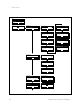
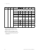
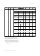
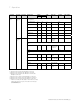
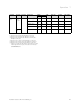
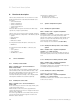
Selection
level 1
Selection
level 2
Selection
level 3
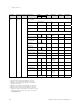
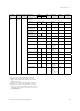
Setting level Values Unit Step size,
select
Factory
reset
Own setting
min. max.
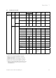
Installer
level
System
configura-
tion
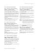
HEATING 2
2)
Circuit type Inactive Active Inactive,
active, zone
Active
Auto day temp until Current value hr:min
Room temp. target
(Day temperature)
530°C0.5 20
Room temp. currant
(Room temperature)
Current value °C
Set-back temp.
(Night temperature)
5 30 °C 0.5 15
Flow temp. target Current value °C
Flow temp. current Current value °C
Pump status Current value On, Off
Mixer status Current value Opening,
Stationary,
Closing
Room temp control None,
Modulation,
Thermost.
None
Summer mode offset 0 30 K 1 1
Heat curve 0.20 4.0 0.05 1.2
Min. temperature 15 90 °C 1 15
Max. temperature 15 90 °C 1 75
System off mode Eco,
Set-back,
Frost prot.
Frost prot.
Advanced functions Current value None,
Away from
home,
At home,
Party function,
Cyl. boost
None
Tab. 7.1 Installer level overview
1) Appears only if solar module VR 68/2 is connected.
2) Appears only if mixing module VR 61/2 is connected.
3) Appears only if mixing module VR 61/2 or solar module
VR68/2 is connected.
4) Appears only if cylinder actoSTOR VIH RL is connected.
5) Appears only if remote control unit VR 81/2 is connected.
6) Appears only if no mixing module VR 61/2 is connected.
* If there is no fault, then the status is "OK". If there is a fault,
"Fault" appears here and you can read the error message
(¬Section10.2) here.