
Technical data
Installation
Installation instructions VRC 470 0020116690_00
11
4
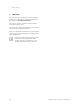
If there are horizontal plug connections without pins on
the control cabinet:
1
2
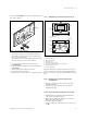
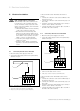
Fig. 4.1 Connecting the pin header
> Connect the 3-way pin header supplied with the con-
troller with the short ends in the 3 horizontal open-
ings on the controller PCB.
> Carefully push the controller with the pin header into
the plug connection of the control cabinet.
> If not already done, mount the external sensor
(¬Section4.5).
> Perform electrical installation of the external sensor
(¬Section5).
> Switch on the power supply to the boiler.
> Bring the boiler into operation.
> If necessary, close the front cover of the boiler again.
4.4 Mounting the controller in the living room
3
4
4
7
6
5
3
2
1
3
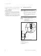
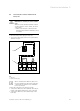
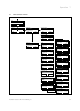
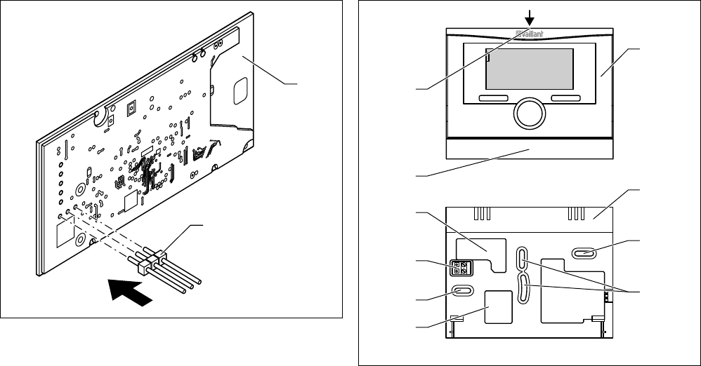
Fig. 4.2 Mounting the controller
1 Controller VRC 470
2 Wall mounting base
3 Mounting holes
4 Openings for cable entry
5 Pin header with terminals for the eBUS cable
6 Wall mounting base cover
7 Slot for screwdriver
Before mounting the controller in the living room, you
must disconnect the controller from the wall mounting
base. You can then secure the wall mounting base to the
wall.
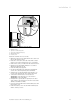
4.4.1 Removing the controller from the wall
mounting base
> Insert a screwdriver into the slot (7) on the wall
mounting base (2).
> Carefully lever the controller (1) out of the wall
mounting base (2).
4.4.2 Secure the wall mounting base to the wall
> Mark the position on the wall. Take the eBUS line
route into account when doing so.
> Drill two holes with 6 mm diameter in accordance
with the mounting holes (3).
> Insert the wall plugs supplied.
> Insert the eBUS cable through one of the cable open-
ing (4).