For the heating engineer Installation and maintenance instructions ecoTEC Gas fired wall hung high efficiency boiler GB VU 656/4
Contents Contents 1 1.1 1.2 1.3 Notes on the documentation........................... Storage of documents ............................................. Safety instructions and symbols ........................... Validity of the instruction manual ........................ 2 2.1 2.2 2.3 2.4 2.5 Description of the boiler .................................. 4 Design .......................................................................... 4 Type summary .....................................................
Contents Notes on the documentation 1 8.8 8.9 Checking the CO2 concentration .......................... 43 Test operation............................................................ 43 9 9.1 9.1.1 9.1.2 9.1.3 9.1.4 9.2 9.3 Troubleshooting ................................................ 44 Diagnostics ................................................................. 44 Status codes ............................................................... 44 Diagnosis codes .........................................
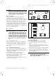
2 Description of the boiler 2 2.1 Description of the boiler Design 1 2 18 3 17 4 5 6 16 7 15 14 8 9 13 10 12 11 Fig. 2.
Description of the boiler 2 Safety instructions and regulations 3 2.2 Type summary Boiler type Designated country Category of permit (designation in accordance with ISO 3166) ecoTEC VU GB 656/4-5 H GB (Great Britain) IE (Eire) I2H Type of gas Nominal heat output range P (kW) Natural gas H - G20 - 20 mbar 13,8 - 63,7 (80/60 °C) 14,1 - 65,7 (60/40 °C) 14,6 - 67,6 (50/30 °C) 14,9 - 69,2 (40/30 °C) Table 2.1 Type summary 2.
3 Safety instructions and regulations • Notify the gas supply company or National Grid Transco 0800 111999 by telephone from outside the building! 3.1.3 Changes to the surroundings of the boiler Changes may not be made to the following equipment: – the heating appliance, – gas, supply air, water and power lines– flue gas removal system, – drain line and expansion relief valve for heating water, – constructional conditions that could affect the operational reliability of the boiler. 3.
Safety instructions and regulations 3 h Note! If the boiler is to be installed in a timber framed 1103 15 building, it should be fitted in accordance with "IGE/UP/7 Edition 2 Gas installations in timber framed and light steel framed buildings". Flue pipe d Danger! Vaillant appliances are only system-certified if genuine Vaillant flue pipes are used. Only use genuine Vaillant flue pipes. Malfunctions can occur if you use other accessories. These may result in damage and injury.
3 Safety instructions and regulations Q I Q Q P F D, E G A I N O C M B L N H H M J K Fig. 3.3 Termination of the flue pipe The flue assembly shall be so placed or shielded as to prevent ignition or damage to any part of the building. Location A B C D E F G H I J K L M Directly below an opening, air brick, opening windows, etc. Above an opening, air brick, opening window, etc. Horizontally to an opening, air brick, opening window, etc. Below temperature-sensitive building components e.
Safety instructions and regulations 3 Balcony/eaves Gutter Flue pipe adequately fixed Flue pipe must project beyond every overhang Fig. 3.4 Termination of flue pipe under balcony or eaves 3.4 Air supply Detailed recommendations for air supply are given in BS 5440: Part 2. It is not necessary to have an air vent in the room or internal space in which the boiler is installed. 3.5 Compartment ventilation The boilers are very high efficiency appliances.
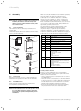
4 Assembly 4 Assembly a Caution! Flush the heating installation thoroughly before installing the boiler to remove foreign substances such as solder and flux residue, leftover sealant or dirt. 4.1 Scope of delivery The Vaillant ecoTEC is delivered pre-mounted in a package unit. Check that all parts have been delivered and are intact (see Fig. 4.1 and Table 4.1).
Assembly 4 4.4 Dimension drawing and connection dimensions 480 472 Ø 80/125 211 94 119 A 1 800 2 4 5 Ø 25, R1 7 Rp 1 6 G 1 1/2 R 3/4 Rp 1 G 1 1/2 172 172 R1 140 61 32 3 8 9 10 75 121 224 224 11 Fig. 4.
4 Assembly 4.5 Required minimum gaps/assembly clearances For the installation/assembly of the boiler as well as for carrying out future maintenance tasks, you need the minimum gaps and assembly clearances given below: 4.7 Mounting the boiler d Danger! Danger of personal injury and damage to property from falling boiler! When assembling the boiler make sure that the fixing point has a sufficient load-bearing capacity. Also take the condition/nature of the wall into account.
Assembly 4 Installation 5 4.8 Removing/attaching the front casing 5 Installation d Danger! Danger of injury to persons and/or material damage due to improper installation! The Vaillant ecoTEC boiler may only be installed by a recognised skilled trade company. who also assumes the responsibility for proper installing and initial start-up of the boiler. 2 1 Take particular care to fit the siphon cartridge during installation.
5 Installation Selection of the low loss header The low loss header uncouples the boiler from the heating system. A sufficiently large water volume is constantly supplied through the boiler via the low loss header in conjunction with the boiler pump. It acts as a neutral point in the system and has minimal hydraulic resistance, therefore the boiler pump does not affect the circuit pumps and vice-versa. A suitable WH type low loss header can be chosen from Table 5.1.
Installation 5 Safety devices • The outlet of the pressure relief valve must be suitably terminated in accordance with BS 6798 or BS 6644. • The boiler is suitable for connection to plastic centralheating pipes. It is preferred that the connections to the boiler are made in copper for the first 1.5 metres prior to the transition to plastic.
5 Installation 5.1 Heating mode In case of only one heating circuit to be operated downstream of the low loss header, this one can directly be controlled by the ecoTEC. A suitable pump can be selected and installed downstream of the low loss header. You can select a pump that fits to your system. In case of systems with multiple circuits please pay attention to the additional control system accessories.
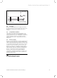
Installation 5 Use the mounted ProE plug (1) to establish the electrical connection for the cylinder charging pump. The pink plug-in location X6 (1) on the PCB is reserved for the cylinder primary pump. It is not necessary to do settings at any diagnosis point. The low loss header ensures, in conjunction with the boiler circulation pump, that a sufficiently high minimum quantity of water is always circulating through the boiler. 5.
5 Installation 5.4 5.5 Gas connection d Danger! Danger of injury to persons and/or material damage due to improper installation! The Vaillant ecoTEC boiler may only be installed by a recognised skilled trade company who also assumes the responsibility for proper installation and initial start-up of the boiler. The legal directives and the local regulations for gas supply companies must be observed.
Installation 5 5.6 Expansion relief valve (safety group), heating installation 5.7 Condensate drain pipework 1 1 2 2 a b c d 5 3 3 4 Fig. 5.11 Fitting the safety valve The ecoTEC is equipped ex factory with connections for a safety group: • Pressure gauge (1) • Filling device (combined filling and emptying valve) (2) • Connection for expansion vessel (3) • Expansion relief valve (4) As an accessory the expansion relief valve for the heating installation is delivered with the boiler.
5 Installation b) connecting into the internal discharge branch (e.g. sink waste) with an external termination, the condensate draining pipe should have a minimum diameter of 22 mm with no length restriction and should incorporate a siphon with a 75 mm (3) (built into the boiler) seal. The connection should preferably be made down stream of the sink waste siphon. If the connection is only possible upstream, then an air break is needed between the two siphons. This is normally provided by the sink waste.
Installation 5 • Cover the supply line over a length of approximately 2 - 3 cm and insulate the cores. 4 a Caution! Supplying power to the wrong plug terminals of the Pro E system can destroy the electronics. Only connect a 230 Vac live supply to boiler terminal connections marked LNE. 1 2 3 5.8.2 Connecting controllers Mount the controllers in accordance with the corresponding operating and installation manuals. The required connections to the electronic system of the boiler (e.g.
5 Installation • If a weather-compensated or room temperature control system is connected (continuous control connection terminals 7, 8, 9) the bridge between terminal 3 and 4 must remain inserted. • Close the rear cover of the electronic box until it audibly engages. • Lift the electronic box up and press the two clips on the left and right of the box against the side casing of the boiler until they audibly engage. • Mount the front casing (see Chap. 4.8).
Installation 5 5.8.
5 Installation Internal pump Boiler enable connection (factory link fitted) N L 230 volt mains input 9 8 7 Optional ext. controller/room thermostat 7-8-9 (continuous, analogue) + - Bus connection for optional accesories 2 1 Safety circuit connection 0 0 DCF RF AF 6 FB 1 Earth Earth Connector DCF connection Low loss header sensor VRC 430 External sensor Remote control, circulation pump X22 230 V~ Mains voltage 5 4 3 (adjustable in d.26, see table 9.3) white X41 N L Additional relay (e.g.
Start-up 6 6 Start-up a Caution! The boiler must only be operated with its casing properly and permanently closed! Otherwise, under unfavourable conditions, it can result in material damage or even injury or death. 6.2 Filling the system 6.2.1 Preparation of heating water Caution! a Do not add anti-freeze to the system water! Addition of such can attack the boiler seals and ultimately result in damage to the boiler and cause noise during the heating operation.
6 Start-up If the heating installation serves several floors, the values for the water pressure in the system may need to be higher (to avoid the ingress of air). • Flush through the heating system thoroughly before actually filling it. h Note! Use the test program P.0 to bleed the heating system: The boiler does not start up. The internal pump runs intermittently and bleeds the appliance circuit. The pressure is displayed digitally. Ensure that the system pressure does not fall below 0.
Start-up 6 h IfNote! the installation kit is not present, do not operate the boiler. Contact Vaillant customer service. d Danger! If the boiler is operated with an empty condensate siphon, there is danger of poisoning through escaping flue gases. Therefore it is mandatory to fill the siphon in accordance with the accompanying description before start-up. 6.
6 Start-up 6.3.2 Checking the gas flow rate The boiler is fitted with a multifunctional automatic gas valve which ensures that the precise air/gas ratio is provided under all operating conditions. The gas flow rate has been set during production and does not require adjustment. With the front casing fitted check the gas flow rate of the boiler as follows: • Start the boiler by activating the test program P.1 as described in section 9.2.
Start-up 6 • Remove the pressure gauge and re-tighten the sealing screw (1). • Turn on gas at the gas isolation valve. • Make sure that there is no leakage at the sealing screw. • Turn off gas at the gas isolation valve. • Put the front casing back on. • Turn off electrical supply to the boiler. • You must not start up the boiler.
6 Start-up 6.4.2 Cylinder charging • Switch on the boiler and the connected hot water cylinder. • Make sure that the cylinder thermostat is requesting heat. • Push the "i" button. If the cylinder is correctly charged the boiler runs through the status displays "S. 20" to "S. 23", until the boiler is running properly in normal operation and the display "S. 24" appears. • Instruct the user about measures taken to ensure the supply of combustion air and removal of flue gas.
Adapting the boiler to the heating system 7 7 Adapting the boiler to the heating system The ecoTEC boilers are equipped with a Digital Information and Analysis system (DIA system). 7.1 Selection and setting of parameters In the diagnosis mode, you can change various parameters to match the boiler to the heating system. + Table 7.1 shows only those diagnosis points where modifications are possible. All the other diagnosis points are only required for diagnostics and fault repair (see Chap. 9).
7 Adapting the boiler to the heating system Display Meaning Adjustable parameters d. 0 Heating partial load 14 - 65 kW Factory setting 46 kW d. 1 Overrun time of internal pump for heating mode 2 - 60 min 5 min d.
Adapting the boiler to the heating system 7 7.2.1 Setting the heating partial load The output of the boilers is set at 35 kW in the factory. You can specify a value that corresponds to the kW output of the boiler under diagnosis point "d. 0“. 7.2.2 Setting of pump overrun and pump operating mode The pump overrun time for the heating operation is set at the factory to a value of 5 minutes. It can be adjusted through a range of 2 – 60 minutes under diagnosis point "d. 1“. Under diagnosis point "d.
7 Adapting the boiler to the heating system TFlow(target) Set maximum burner blocking time [°C] 1 5 10 15 20 2.0 5,0 10,0 15,0 25 2.0 4,5 9,2 14,0 30 2.0 4,0 8,5 12,5 35 2.0 4,0 7,5 11,0 40 2.0 3,5 6,5 10,0 45 2.0 3.0 6.0 8,5 50 2.0 3.0 5,0 7,5 55 2.0 2.5 4,5 6.0 60 2.0 2.0 3,5 5,0 65 2.0 1,5 2.5 3,5 70 2.0 1,5 2.0 2.5 75 2.0 1,0 1,0 1,0 [min] 20 20,0 18,5 16,5 15,0 13,0 11,5 9,5 8,0 6.0 4,5 2.5 1,0 25 25,0 23,0 20,5 18,5 16,5 14,0 12,0 10,0 7,5 5,5 3.
Inspection and maintenance 8 8 8.1 Inspection and maintenance Inspection and maintenance intervals Danger! Risk of injury and risk of damage to property due to neglected inspection and maintenance! Neglected inspection and maintenance works or not observing the stated inspection and maintenance intervals can interfere with the operational safety of the boiler and can result in damage to property and to persons.
8 Inspection and maintenance - The gas inlet working pressure at maximum rate as described in section 6.3.3. - The gas flow rates as described in section 6.3.2. - Correctness of electrical, water and gas connections. - Correctness of the water pressure. - The condition of the whole system, in particular the condition of radiator valves, evidence of leakage from the heating system and dripping taps. • Correct any faults before proceeding. 8.1.
Inspection and maintenance 8 • Remove the front casing. • Start the testing program P.1. • Wait at least 5 minutes until the boiler reaches its operating temperature. • Measure the CO2 concentration at the flue gas analysis point (1). Compare the measured value with the corresponding value in Table 8.1. • If all these points are as required, proceed as described in section 8.1.5. • If one of the flue gas values is greater than the acceptable values in Table 8.
8 Inspection and maintenance 8.1.5 . Inspection and maintenance work steps Column 2 Maintenance Column 1 must be carried Inspection must out at regular be carried out intervals – but each year no longer than 5 years No. Activity 1 Check the air flue gas installation for leaks and for proper fixation and ensure it is not blocked or damaged and is fitted correctly, complying with the relevant installation instructions.
Inspection and maintenance 8 8.2 Filling/draining the boiler and heating installation 1 2 8.2.1 Filling the boiler and the heating installation A description of how to fill the boiler and heating installation is provided in Chap. 6.2. 3 8.2.2 Draining of the boiler • Close the service valves of the boiler. • Open the drain valve on the return line connection. • To drain the boiler completely, open: - the automatic air vent on the air separator, - the bleed nipple on the flow line connection. 8.2.
8 Inspection and maintenance H Danger! Danger of combustion and damage due to escaping hot flue gases! The silicone seal and the silicate cord on the compact thermal module (No. 180904) must be replaced at every maintenance operation. The insulating layer on the burner door (No. 180913) must not exhibit any signs of damage; otherwise it must also be replaced (see Chap. 8.3.4). 8.3.2 Cleaning the heat exchanger 8.3.3 Checking the burner The burner is maintenance-free and needs no cleaning.
Inspection and maintenance 8 1 2 3 4 5 6 1 Fig. 8.6 Checking for gas tightness 7 a Caution! Open the gas feed and check the gas tightness 10 9 of the boiler with leak detector spray. Check the screwed connection (1) particularly carefully. 8 Fig. 8.5 Installing the compact thermal module • Insert the compact thermal module (6) into the heat exchanger (1).
8 Inspection and maintenance After that, both can be cleaned in the dismounted state. Take note also of the accompanying installation manual for the siphon cartridge. 8.5 Cleaning the air separation system H Danger! Danger of burning or scalding! All water-carrying components present a danger of injury and scalding. Only carry out work on these components if they have cooled down. • Drain the boiler (see Chap. 8.2.2). 1 1 2 3 4 Fig. 8.
Inspection and maintenance 8 a Caution! All O-rings must be replaced with new ones as otherwise leaks may occur! • Screw the brass cover onto the air separator. • Reassemble the air separator in the reverse order. • Fill and bleed the boiler (see Chap. 6.2) 8.6 Checking the charge pressure of the external expansion vessel • Measure the charge pressure of the expansion vessel at the testing nozzle of the vessel when the aplliance is depressurised.
9 Troubleshooting 9 Troubleshooting h Note! Whenever possible, please quote the fault code displayed (F.xx) and the status of the boiler (S.xx) when contacting the Vaillant customer service or your Vaillant service partner. 9.1 Diagnostics 9.1.1 Status codes The status codes that you can see on the display provides information about the current operating condition of the boiler. The display of the status codes can be viewed as follows: Display Meaning Heating S.0 S.1 S.2 S.3 S.4 S.5 S.6 S.7 S.
Troubleshooting 9 9.1.2 Diagnosis codes In the diagnosis mode, you can change certain parameters or display more information. The diagnosis information is divided into two diagnosis levels. The 2nd diagnosis level can be reached only after entering a password. a Caution! The access to the 2 nd diagnosis level may only be used by a qualified heating engineer. 1st diagnosis level • Push the "i“ and "+“ buttons simultaneously. The display shows "d.0“.
9 Troubleshooting Display Meaning Display value/adjustable value d.0 Heating partial load d.1 d.2 Pump overrun for heating mode Maximum blocking time heating at 20°C flow temperature Measured value of cylinder sensor Target value of flow temperature (or target value of return) Adjustable heating partial load in kW (factory setting: approx. 70% of maximum output) 2 - 60 minutes (factory setting: 5) 2 - 60 minutes (factory setting: 20) d.4 d.5 in °C in °C, maximum of the value set in d.
Troubleshooting 9 Display Meaning Display value/adjustable value d.14 Pump speed target value d.17 Heating flow/return regulation changeover Target value of internal pump in % Possible settings: 0 = auto (factory setting) 1 = 53 2 = 60 3 = 70 4 = 85 5 = 100 (factory setting) 0 = flow, 1 = return (factory setting: 0) d.18 Specifying the pump operating mode d.20 Maximum setting for cylinder target value d.26 Additional relay control ecoTEC 1 = circulator 2 = ext.
9 Troubleshooting Display Meaning Display value/adjustable value d.81 Operating hours hot water generation in h1) d.82 Burner start-ups in heating mode Number/1001) (3 equals 300) d.83 Burner start-ups in hot water mode Number/1001) (3 equals 300) d.84 d.93 Maintenance indicator: Number of hours until the next maintenance DSN appliance variant setting Setting range: 0 to 3000h and "-“ for deactivated Factory setting: "-“ (300 corresponds to 3000h) Setting range: 0 to 99 d.
Troubleshooting 9 Code F. 0 Meaning Interruption, flow temperature sensor Cause NTC plug not plugged in or has come loose, multiple plug on electronics not plugged in correctly, interruption in cable harness, NTC defective NTC plug not plugged in or has come loose, multiple plug on electronics not plugged in correctly, interruption in cable harness, NTC defective F. 1 Interruption, return temperature sensor F.10 F.
9 Troubleshooting Code F.72 Meaning Flow and/or return temperature sensor fault Cause Temperature difference between flow temperature sensor and return temperature sensor too great -> flow and/or return temperature sensor defective Interruption/short-circuit of water pressure sensor, interruption/ short-circuit to GND in supply line to water pressure sensor F.73 Error in water pressure sensor F.
Replacing components 10 10 Replacing components 10.2 The tasks listed below in this section may be carried out only by a heating engineer. • Only use genuine spare parts for repairs. • Make sure the parts are correctly fitted and that their original position and alignment are retained. d Danger! Before replacing the component, observe the 10.1 Replacing the burner safety information in Chap. 10.1. • Dismount the compact thermal module as described in Chap. 8.3.1.
10 Replacing components 11 Vaillant Service 12 Recycling and disposal 10.4 Replacing the heat exchanger d Danger! Before replacing the component, observe the The electronics is now set to the boiler type and the parameters of all adjustable diagnosis points correspond to the factory settings. You can now make the specific settings for the system. safety information in Chap. 10.1. • Observe the installation manual that accompanies the spare part.
Technical data 13 13 Technical data ecoTEC VU 656/4 unit Heat Output Range (heating 50/30 °C) 14,6 - 67,6 kW Heat Output Range (heating 80/60 °C) 13,8 - 63,7 kW Maximum Heat Input (Net) 65 kW Net Efficiency at 100% load 98 % Net Efficiency at 30% load 108 % SEDBUK rating A SAP seasonal Efficiency 90,5 % Inlet gas working pressure required (natural gas) 20 mbar NOx class 5 - NOx level 55 mg / kW hr CO2 Percentage (after 5 minutes full load +/- 1) 8,8 % Recommended CO lev
0020029173_01 GB 082010 – Subject to alterations