
Installation Manual

Instructions for installation and servicing ecoTEC plus 0020020828_0746
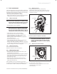
• Remove the clip securing the clear condense pipe
to heat exchanger.
• Pull to remove clamps (two at the top and one at the
bottom) to remove the heat exchanger, see fig 11.2.
h
Note!
There will be water in the heat exchanger.
• Remove clear condense pipe connector from bottom
of heat exchanger.
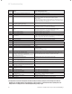
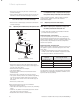
11.6 Replacing the condense trap and siphonic drain
adapter
float
condense trap
screw
spigot
s
p
i
g
ot bun
g
(remove and discard)
Fig. 11.3 Condense trap
• Remove the clips securing the flexible tubes to the
adapter by twisting the clips slightly to disengage the
clip jaws from each other.
• Remove flexible tubes from adapter.
• Lift off the adapter.
• Remove the drain connection downstream of the
condense trap.
• Remove the two condense trap securing screws.
• Lift up and carefully remove the condense trap taking
care not to spill any water which may be left in the
unit. As the unit is lifted remove the flexible pipe on
the outlet.
• Remove any solids found.
Before removing the float note it’s orientation.
• Remove the float to clean it.
• Flush water through the trap to remove any remaining
solids.
• Check for any debris in the outlet pipe of the conden-
sate drain and clean as necessary.
• Reassemble and refit the condense trap.
h
Note!
If a replacement trap is required remove spigot
bung before fitting condensate drain connection.
Using a suitable container, flush the heat exchanger
until the water appears clear in the container.
Reassemble adapter.
11.7 Replacing electronics and display
d
Danger!
Before replacing the component, comply with
the safety instructions in Section 11.1.
• Comply with the assembly and installation manuals
provided with the spare parts.
Replacing display or electronics
If you are replacing only one of the two components,
the parameter adjustment functions automatically. On
turning on the appliance, the new component takes over
the previously set parameters from the components
that are not replaced.
Replacing display and electronics
When replacing both components, after being turned on,
the appliance goes to fault and displays the error mes-
sage “F70”.
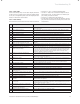
• In the second diagnostic level, under the diagnostic
number “d.93” enter the number of appliance variant
according to Table 11.1 (see section 10.1.2).
Appliance Device specific number
ecoTEC plus 415 11
ecoTEC plus 418 12
ecoTEC plus 428 13
ecoTEC plus 438 14
Table 11.1 Device specific numbers
The electronics is now set to the appliance type and the
parameters of all adjustable diagnostics numbers corre-
spond to the factory settings.
11 Parts replacement