
Installation Manual
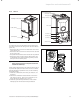

Instructions for installation and servicing ecoTEC plus 0020020828_0738
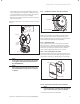
• Remove valve cap from expansion vessel charge point.
• Check that the internal charge pressure of the expan-
sion vessel is to the correct design pressure. If the
pressure is lower than this the vessel should be re
pressurised using an air pump.
• Refit the valve cap.
• Re pressurise boiler and heating system.
8.1.11 Re commissioning the boiler
• Carry out electrical safety checks.
• Turn on the electrical supply.
• Open the boiler CH service valves.
• Carry out function checks of boiler operation as previ-
ously detailed.
• Check gas rate as previously detailed.
• Check for water leaks.
• Refit case, ensuring that a good seal is obtained.
8.1.12 Test operation
Always perform the following checks after completing
any maintenance task:
• Commission the appliance according to the relevant
operating manual.
• Check the appliance for gas and water leaks.
• Check the air/flue gas system for leaks, check its
fastening
• Check for ignition and an even flame on the burner.
• Check that the heating system is working.
• Fill out the Benchmark gas boiler commissioning
checklist at the rear of this guide.
9 Combustion analysis
h
Note!
The boiler is fitted with a flue gas analysis
point. A suitable flue gas analyser can be con-
nected to this point to establish the combus-
tion performance of the boiler.
9.1 Check
CO
2
content
Refer to table 9.1 and if necessary set (air-ratio adjustment).
h
Note!
Combustion analysis must be carried out at an-
nual service if a flue gas analyser is available, if
no analyser is available then visual checks
should be carried out as per service schedule.
Checking/adjustment of this value is also re-
quired in the following instances: replacement
of gas valve, conversion to or from natural gas/
LPG or if incorrect combustion is suspected!
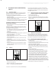
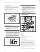
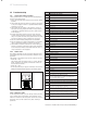
flue gas analysis point
Fig. 9.1 Analysis point
• Remove the front and inner cover.
• To correct combustion follow the procedure as listed
below.
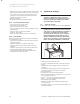
• Ensure that the gas supply pressure is correct (see
table 5.1)
• The gas inlet working pressure can be checked at the
pressure test point on the gas valve (fig 5.3.).
• Turn gas supply on.
• Ensure there is an external heat demand.
• Enter the test programs by holding the “+” key, see fig
6.2. and turning power on.
• Press “+” until “P.1” is displayed for max rate.
• Press “ i ” to operate appliance in this mode.
• Allow appliance to stabilise.
• Measure the CO2 at the combustion analysis point
point, see fig 9.1.
• Check CO2 value (for case off) as stated in table 9.1 for
the boiler installed.
8 Inspection and maintenance
9 Combustion analysis