
Installation Manual

Instructions for installation and servicing ecoTEC plus 0020020828_0736
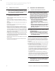
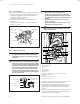
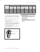
8.1.5 Spark electrode
• Disconnect the ignition lead and earth lead from the ignit-
er unit and two securing screws at the spark electrode.
• Withdraw the spark electrode carefully from the
combustion chamber, see fig 8.4.
• Inspect the tips for damage.
• Clean away any debris and check the spark gap is
3.5 -4.5 mm.
• Check the electrode gasket for signs of damage and
replace if necessary.
spark gap 3.5 to 4.5 mm
heat exchanger
spark electrode
securing screw 2 off
earth lead
gasket
Fig. 8.4 Withdrawing the spark electrode
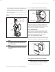
8.1.6 Removing the burner
h
Note!
If the functional checks did not indicate poor
combustion then it is not necessary to service
the burner.
a
Caution!
The burner door seal and combustion chamber
burner door securing nuts on the burner module,
see figs 8.6 and 8.7 must be replaced each time
the module is removed for example during main-
tenance if the burner flange insulation shows
any signs of damage or small cracks it must
also be replaced. Isolate the gas supply at the
gas service cock. Disconnect the gas supply at
the gas service cock.
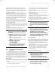
sealing grommet
gas pipe bracket
securing screw
condense
trap
union nut
gas service cock
gas supply pipe in
Fig. 8. 5 Gas service cock
h
Note!
• Do not disconnect at the gas valve.
• Remove the two gas pipe bracket securing
screws from underside of inner case, see fig 8.5.
• Drop down the electronics box into the service
position.
• Remove the four screws from the chassis
front, see fig 8.2.
• Remove the chassis front by pulling it out at
the top from its retaining slots.
h
Note!
When replacing chassis front panel ensure the
bottom fits behind lip.
1
2
3
4
5
6
7
8
9
10
11
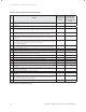
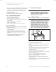
Fig. 8.6 Fan, gas valve and burner
1 Electrode connector
2 Ignition lead
3 Fan
4 Electrical lead
5 Gas pipe bracket
6 Burner door
7 Combustion chamber burner door securing nuts (5 off)
8 Earth spade connector
9 Gas valve
10 Chassis front retaining slots
11 Gas valve electrical plug
• Disconnect the gas valve electrical plug at the gas valve.
• Disconnect the electrical leads from the fan.
• Remove the five combustion chamber burner door
securing nuts, these should be discarded and replaced
with the new nyloc nuts supplied in the burner door
seal kit.
• Gently remove the fan, gas valve and burner assembly
from the combustion chamber complete with the gas
pipe bracket and seal, see fig 8.6.
8 Inspection and maintenance