
Installation Manual

35Instructions for installation and servicing ecoTEC plus 0020020828_07
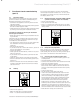
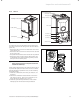
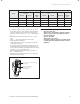
8.1.4 General
retaining dowel (2 off)
front casing
screw (2 off)
Fig. 8.1 Panels
All routine servicing requirements can be achieved by
the removal of the front casing, inner case and chassis
panel only.
• Remove the two screws on the underside of the front
casing and lift off.
• Remove the two screws on the front of inner case and
lift off, see fig 8.1.
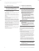
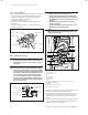
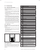
• Drop down the electronics box into the service position.
• Remove the four screws from the chassis panel, see
fig 8.2. Remove the chassis panel by pulling it out at
the top from its retaining slots.
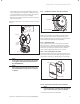
h
Note!
When replacing chassis front panel ensure the
bottom fits behind lip.
Unless stated otherwise any part removed during servic-
ing should be replaced in the reverse order to removal.
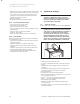
With the appliance operational carry out the following
functional checks:
1. Check the combustion, with a flue gas analyser, see
section 9.
2. Should the combustion measurement or flame and
gas valve be correct, then it is not necessary to re-
move the burner assembly for a service.
3. Check the operational performance of the central
heating agrees with the technical specification.
flue gas analysis point
combustion air
analysis point
retaining dowel (2 off)
inner case
chassis panel
screw (2 off)
screw (4 off)
electronic box
Fig. 8.2 Control panel
viewing window
Fig. 8.3 Flame picture
Inspection and maintenance 8