
Installation Manual

Instructions for installation and servicing ecoTEC plus 0020020828_0730
6 Natural gas to LPG conversion
6 Natural gas to LPG conversion
The ecoTEC plus is able to be field adjusted for use on
LPG – propane G31 gas. To enable conversion the use of
a flue gas analyser is necessary.
a
Caution!
After converting from natural gas to LPG, com-
mission and check boiler function as described
in commissioning section of the servicing and
installation instructions.
a
Caution!
This conversion must only be carried out by a
competent person approved at the time by the
Health and Safety executive and in accordance
with the gas safety (installation and use) regu-
lations 1998.
Before starting any work:
• Isolate the electrical supply to the boiler.
• Turn off the gas supply at the gas service cock fitted
to the appliance.
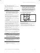
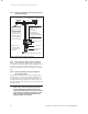
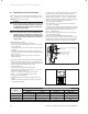
• Turn the gas valve “A” throttle screw (Ref fig.6.1) fully
clockwise.
• Turn the “A” throttle screw back anti-clockwise the
required number of turns as stated in Table 9.1 for the
boiler installed.
• Ensure the gas analyser is set to the correct fuel
setting propane.
To obtain conversion follow the procedure as listed below.
•
Ensure that the gas supply pressure is in the range 34 - 37
mbar. The gas inlet working pressure can be checked at the
pressure test point on the gas valve (fig 5.3.).
• Turn gas supply on.
• Ensure there is an external heat demand.
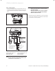
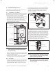
• Enter the test programs by holding the “+” key, see
fig 6.2. and turning power on.
• Press “+” until “P.1” is displayed for max rate.
• Press “ i ” to operate appliance in this mode.
• Allow appliance to stabilise.
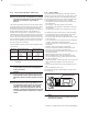
• Measure the CO
2
at the flue gas analysis point, see
fig 9.1.
• Check CO
2
value (for case off) as stated in table 6.1
for the boiler installed.
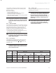
Model
LPG
G31 % CO
2
after 5mins at full load Throttle Maximum
Case off Case on Adjustment CO/CO
2
ratio
ecoTEC plus 415 10.1 + 0.5 - 0.5 10.3 + 0.5 - 0.5 5 turns
<0.0026
ecoTEC plus 418 10.1 + 0.0 - 1.0 10.3 + 0.0 - 1.0 5 turns
<0.0026
ecoTEC plus 428 10.5 + 0.3 - 0.8 10.7 + 0.3 - 0.8 5 turns
<0.0026
ecoTEC plus 438 9.8 + 0.2 - 0.8 10.0 + 0.2 - 0.8 8 turns
<0.0026
Table 6.1 LPG settings
• If required, using a screwdriver, adjust the “A” throttle
to obtain correct value. (rotating anti-clockwise to
increase). Appliance will remain in this mode for 15 mi-
nutes or exit by pressing “ i ” and “+” simultaneously.
• Repeat the process above and select “P.2” for min rate.
• Press “ i ” to operate appliance in this mode.
• Allow appliance to stabilise.
• Check CO
2
value (for case off) as stated in table 6.1
for the boiler installed.
• If required, using a 2mm allen key, adjust the “B” offset
to obtain correct value. (rotating clockwise to increase)
• After checking the combustion, exit by pressing “ i ”
and “+” simultaneously
• Refit the chassis panel and the inner case. (Note the
CO
2
will increase slightly).
• Fit the LPG conversion label to the type plate.
• Lift the control box into place and fit the front casing.
• Commission the boiler as described in the Installation
and Servicing Instructions supplied with the boiler.
"A" throttle – "Pmax" rotate
to increase
"B" offset adjustment
"Pmin" rotate
to increase
Fig. 6.1 Gas control valve
Fig. 6.2 ecoTEC plus controls