
Installation Manual

Instructions for installation and servicing ecoTEC plus 0020020828_0724
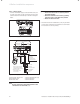
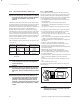
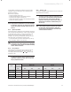
NTC return
NTC flow
X 20/5 red
X 20/7 black
X 20/8 blue
black link
Ignition electrode
Fan unit
Gas valve assembly
X 20/18 red (24 Vdc)
X 20/9 blue (earth)
Chassis earth
green/ yellow
pump connection
red
red
fuse T2E
250 Volts
Electronic control box
green/yellow
green/ yellow
bus 24 V
230 V
X20
black
X2
X 20/16 blue (earth)
X 20/4 grey (PWM)
X 20/3 black (hall signal)
X 20/17 red (24 Vdc)
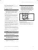
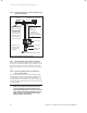
Fig. 4.10 Mains Supply Connection
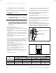
4 Boiler installation sequence