
Installation Manual

23Instructions for installation and servicing ecoTEC plus 0020020828_07
Boiler installation sequence 4
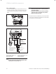
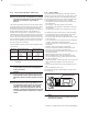
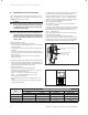
4.4.3 Electrical board layout
X20 X2
-+
BUS 24V 230V
789 LN 345
X40 X41
X31
Caution:
Do not connect
supply voltage!
Risk of damage
to electronics!
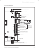
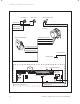
Room thermostat 24V:
Connection 7, 8 and 9
No bi-directional
interface (analogue only)
Mains supply: 230V / 50Hz
Room thermostat 230V / 50Hz
(remove bridge on connection)
Heating pump
2A fuse, slow
Igniter
Connection: 230V
Su
pp
ly for accessory module
eBUS accessory connection
Burner cable harness
Accessory module connection
Diagnosis via eBUS
vrnet DIALOG
outer probe
ext. flow or return probe
Hydraulic cable harness
Connection for external
eBUS controller
ext. flow or return probe
X12
Fig. 4.9 Connection wiring