
Installation Manual

21Instructions for installation and servicing ecoTEC plus 0020020828_07
Boiler installation sequence 4
4.3.6 Installing the flue system
• Install the flue system (refer to the separate air/flue
duct installation instructions).
4.4 Electrical connections
e
Danger!
This appliance must be earthed. Electrocution
caused by touching live parts can be fatal.
Before working on the appliance, turn off the
power supply and secure against restart.
• The boiler must be earthed.
• All system components shall be of an approved type
and all wiring to current I.E.E. wiring regulations.
• External wiring must be correctly earthed, polarised
and in accordance with the relevant standards.
- In GB this is BS 7671.
- In IE this is the current edition of I.S.813 “Domestic
Gas Installations”.
• The boiler must be connected to a permanent 230V
ac, 50Hz supply.
• Connection of the whole electrical system of the boil-
er, inclu-ding any heating controls, to the electrical
supply must be through one common isolator and
must be fused 3 Amp maximum.
• Isolation should be by a double pole switched fused
spur box, with a minimum gap of 3 mm for both poles.
The fused spur box should be readily accessible and
preferably adjacent to the appliance. It should be
identified as to its use.
• Alternatively connection can be made through an un-
switched shuttered socket and 3A fused 3-pin plug
both to the current issue of BS 1363 may be used, pro-
vided they are not used in a room containing a bath or
shower.
• A 3 core flexible cord according to BS6500 tables 6,
8 or 16 (3 x 0.75 to 3 x 1.5mm2) should be used.
a
Caution!
This appliance must be wired in accordance
with these instructions. Any fault arising from
incorrect wiring cannot be put right under the
terms of the Vaillant guarantee.
e
Danger!
Mains connection terminals L and N remain live
“unless isolated at the fused spur or electrical
outlet supplying the boiler”.
a
Caution!
Do not connect any mains 230V power to the
connections 7-8-9 or BUS (+,-).
h
Note!
Ensure that all cables pass through grommets
in the outer casing and are securely fixed by
the cable clamps in the rear of the electronics
box. Ensure that the power supply is connected
such that the current carrying conductors
become taut before the earth conductor should
the supply cable slip from the cable clamp.
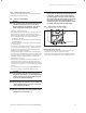
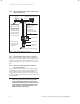
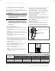
4.4.1 Connection to the main supply
• Lower the electronics box, see fig. 4.7.
unclip
electronics box
Fig. 4.7 Mains Supply Connection
Opening the electronics box
• Unclip the bottom of the electronics box cover and
hinge back to reveal the connection plugs.
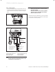
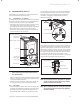
• Feed the power supply flex into the appliance and the
electronics box through the cable clamps provided.