
Installation Manual

19Instructions for installation and servicing ecoTEC plus 0020020828_07
h
Note!
Care should be taken not to scratch the white
surface of the boiler casing.
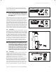
4.2 Flue exit
Refer to flue system installation instructions for full de-
tails.
d
Danger!
Vaillant appliances are certified only for use
with ge-nuine Vaillant flue pipes. Only use gen-
uine Vaillant flue pipes. Malfunctions can occur
if you use other accessories. These may result
in damage and injury. You will find a list of gen-
uine flue pipes in the Vaillant installation man-
ual for flue pipes. The CE mark is valid only if
the appliance is operated with Vaillant flue
pipes.
4.2.1 Other flue options
Flue instructions for other flue systems such as vertical
RSF flues, flues run to the side of the boiler and the use
of additional bends etc. are detailed in the flue installa-
tion instructions.
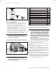
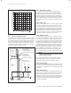
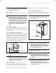
4.3 Fitting the boiler hanging bracket
Reposition the wall template over the flue hole ensuring
the template is vertical and mark the position of the fix-
ing holes for the hanging bracket, see fig 4.3. Mark and
drill the fixing holes and secure the hanging bracket. Fix
the hanging bracket to the wall using the screws sup-
plied. Ensure the uppermost set of screw positions are
used (it may be necessary to use additional or alterna-
tive fixings to ensure adequate support).
wall plug (4 off)
wall template
hanging bracket
screw n° 12 x 50 mm (4 off)
160
Fig. 4.3 Boiler hanging bracket
h
Note!
If the boiler is to be fitted in a timber framed
building ensure that the bracket is secured to
a substantial part of the timber frame capable
of taking the weight of the boiler.
4.3.1 Boiler fixing
Lift the boiler into position in the following manner:
Lean the top of the boiler slightly to the wall and posi-
tion just above the hanging bracket. Allow the boiler to
slowly move downwards until engaged in the hanging
bracket.
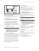
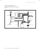
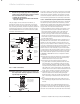
4.3.2 Removing the front casing
Remove the front casing securing screws then lift the
case upwards off the two top retaining dowels, see fig
4.4.
h
Note!
Take care not to damage the front casing.
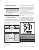
4.3.3 Gas connection
retaining dowel (2 off)
front casing
screw (2 off)
Fig. 4.4 Removing front casing
d
Danger!
The gas connection may only be made by a
competent person approved at the time by the
Health and Safety Executive. The legal direc-
tives and the local regulations for gas supply
companies must be observed.
a
Caution!
Ensure a stress-relief assembly of the gas
pipes to avoid leakages!
a
Caution!
The gas regulating block may be tested for
leakage only with a maximum pressure of 150
mbar! Higher testing pressures can damage the
gas fitting.
a
Caution!
When making final connection to the boiler, if
using soldered fittings, extra care should be
taken to avoid damage to isolation valves
through heat transfer. Before connection check
the supply of local gas.
Boiler installation sequence 4