
Technical data


Replacing components
74 Installation and maintenance instructions ecoTEC plus 0020116700_06
14
i
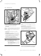
The plug on the venturi has latching lugs with
which it engages in the slot. You have to release
the latching lug by pushing it in to pull off the
plug.
> Remove the plug from the sensor of the venturi
(1,¬fig.14.8).
> Unscrew the two cap nuts at the top (5, ¬fig.14.8) and
bottom (4, ¬fig.14.8) of the gas valve. Counterhold at
opposite side of gas valve when unscrewing, or unscrew
both cap nuts at the same time.
> Unscrew the fixing screw of the gas valve (3, ¬fig.14.8)
out of the bracket.
i
Since the fixing screw is difficult to access
beneath the retaining plate, alternatively, you
can remove the entire fan assembly
(¬section14.3).
> Remove the gas valve from the bracket.
> Refit the new gas valve in the reverse order. Use new
seals.
> When the cap nuts are being screwed to the gas valve,
counterhold at the opposite side of the gas valve or
tighten both cap nuts simultaneously (¬fig.14.6).
> After installing the new gas valve, perform a gas family
check (¬section12.1.5) and a gas ratio setting
(¬section10.11).
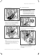
14.5 Replacing the venturi including the mass
flow sensor
1
2
3
14.9 Replacing the venturi including the mass flow sensor
> Remove the air intake pipe (¬section12.4.1).
> Remove the plug from the sensor of the venturi
(1, ¬fig.14.9).
> Unscrew the cap nut (3 ¬fig.14.9) of the gas connecting
pipe (2 ¬fig.14.9) from the gas valve.
> Remove the venturi including the gas supply pipe from
the fan by turning the bayonet fitting on the venturi anti-
clockwise as far as it goes and removing it from the fan.
2
1
6
5
4
3
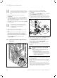
14.10 Removing the gas connecting pipe
> Remove the gas connecting pipe (1, ¬fig.14.10) from the
venturi (2 ¬fig.14.10) by detaching the clamp
(3, ¬fig.14.10) and pulling out the gas connecting pipe
vertically. Dispose of the seal (6, ¬fig.14.10).
> Pull off the gas restrictor (5, ¬fig.14.10) in a straight
direction, and dispose of it.
> Check whether the venturi is free of residue at the gas
inlet side.
a
Danger!
Risk of poisoning due to increased CO
levels!
Using the wrong gas restrictor size can
cause higher CO levels.
> When replacing the venturi, ensure that
you use the correct gas restrictor (colour
coding and position of pins on the under-
side of the gas restrictor).
> Insert the gas restrictor for the gas group in question
into the new venturi.
Ensure that the colour of the gas restrictor corresponds
with the colour of the coding resistor on the PCB in the
electronics box.
When inserting the gas restrictor, ensure that the gas
restrictor is correctly aligned using the specified position
marks on the top of the venturi and also the positioning
pins (4) on the bottom of the gas restrictor.