
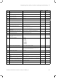
Technical data


Inspection and maintenance
Installation and maintenance instructions ecoTEC plus 0020116700_06 57
12
During any inspection and maintenance or after change of
parts of the combustion circuit, the following must be
checked:
– The boiler has been installed in accordance with the rele-
vant installation instructions.
– The integrity of the flue gas installation and flue seals is
in accordance with the relevant flue installation instruc-
tions enclosed.
– Visual, the integrity of the boiler combustion circuit and
relevant seals (paying particular attention to the burner
door seal).
– The gas inlet working pressure at maximum rate as
described in ¬section10.11.4.
– The gas flow rates as described in ¬section10.11.3.
– Correctness of electrical, water and gas connections.
– Correctness of the water pressure.
– The condition of the whole system, in particular the con-
dition of radiator valves, evidence of leakage from the
heating system and dripping taps.
> Correct any faults before proceeding.
12.1.2 Safety instructions
a
Danger!
Danger of life and limb by electric shock!
The supply terminals of the boiler are
under mains voltage even if the boiler main
switch is off.
> Don’t touch the supply terminals.
> Protect the electronic box from any
water or spray.
> Before working on the boiler, turn off the
power and secure against restart.
i
If it is necessary to keep the electricity to the
boiler switched on for certain inspection and
maintenance, this is indicated in the description
of the maintenance task.
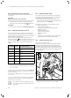
Always perform the following steps prior to inspection or
maintenance work:
> Switch off the main switch.
> Disconnect the boiler from the power mains by
– disconnecting the mains plug or
– de-energising the boiler via an isolating device with a
contact opening of at least 3mm (e. g. fuses or power
switches).
> Further check for electrical isolation of the appliance by
use of a test meter.
> Close the gas isolation valve.
> Close the service valves in the heating flow and return.
> Remove the front casing from the boiler.
> When removing any water carrying components ensure
that water is kept away from all electrical components.
Always perform the following steps after performing any
inspection or maintenance work:
> Always use new seals and O-rings when parts are
replaced.
> Open the service valves in the heating flow and return.
> Open the cold water stop valve if necessary.
> Reconnect the boiler to the power mains.
> Switch on the boiler using the on/off switch.
> Fill the heating circuit of the boiler to a pressure of
between 0,1 and 0,2MPa (1,0 and 2,0 bar) if required.
> If you have topped up with water, purge the heating
installation using test program P.00 (¬section10.7.2).
> Open the gas isolation valve.
> Check the boiler for gas and water leaks.
> Replace the front casing to the boiler (¬section4.7).
> If you have worked on the gas route, carry out a gas
family check (¬section12.1.5).
> Carry out a functional check of the boiler (¬section
10.12).
> Always check earth continuity, polarity and resistance to
earth with a multimeter after any service work and after
replacing any electrical component.
> If necessary, refill and re-purge the heating installation.
> Complete the benchmark gas boiler commissioning serv-
ice record on the back pages of these instructions.
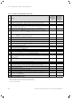
12.1.3 Checking the CO/CO
2
ratio and the CO
2
concentration
a
Danger!
Danger of explosion, fire or poisoning
caused by incorrect flue gas value
adjustment.
Safe combustion can only be verified by
measuring CO/CO
2
ratio.
> Make sure that the CO/CO
2
ratio does not
exceed the value shown in
¬table12.1.
i
Checking/adjustment of the CO2 concentration
is required in the following instances:
- replacement of gas valve,
- conversion to or from Natural Gas/LPG
- or if an incorrect combustion is suspected.