
Technical data

Commissioning
Installation and maintenance instructions ecoTEC plus 0020116700_06 41
10
Display Meaning
P.00
1)
Purging test program
The heating circuit and the hot water circuit are purged
using the automatic air vent (the cap of the automatic
air vent must be released).
1 x right selection button: Start heating circuit purging
2 x right selection button (" -> "): Start purging
hot water circuit
3 x right selection button (" -> "): Restart heating
circuit purging
1 x left selection button ("Cancel"): Exit purging pro-
gram
The internal pump is cyclically actuated.
Note: The purge program runs 7.5min per circuit.
P.01 Maximum load test program:
The boiler is operated at maximum heat input after suc-
cessful ignition.
P.02 Minimum load test program:
The boiler is operated at minimum heat input after suc-
cessful ignition.
P.06 Filling mode test program:
The diverter valve (VUV) is moved to the mid-position.
The burner and pump are switched off (to fill or drain
the boiler).
10.1 Overview of the test programs
1)
Purging the heating circuit:
Diverter valve in heating position, actuation of internal pump
for 9 cycles: 30s on, 20 s off. Display: "Active heating circuit".
Purging the hot water circuit:
After the above-mentioned cycles have run or the right selec-
tion button has been pressed again: Diverter valve in the hot
water position, actuation of the internal pump as above. Display:
"Active hot water circuit".
i
If you do not press a button for more than
15minutes. the test programs are stopped auto-
matically. The boiler switches to normal operat-
ing mode.
To terminate the test programs, you can press the left
selection button ("Cancel") at any time.
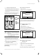
P.00 Exhaust
Cancel
Heating circuit
1,0 bar
10.1 Boiler in error condition
i
If the boiler is in error condition, you cannot
start any test programs. You can detect an error
condition by the fault symbol shown in the left
bottom corner of the display. You must first
reset.
10.5 Preparing the heating water
Pay attention to the specifications concerning heating
water preparation in (¬section2.5.7).
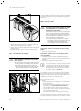
10.6 Read off the filling pressure
The boiler is equipped with an analogue pressure gauge
(¬fig. 3.1 and 3.2) and also has a symbolic bar display for
the filling pressure of the heating installation and a digital
pressure and temperature display.
You can see the pressure gauge once you have removed
the front casing of the boiler.
Press the right selection button twice to read off the digital
filling pressure value.
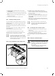
10.7 Filling and purging the heating installation
b
Caution.
Risk of damage caused by contaminated
lines.
Foreign bodies such as welding remnants.
sealing residue or dirt in the water lines can
cause damage to the boiler.
> Flush the heating installation thoroughly
prior to commissioning.
The system is filled via a customer-installed filling connec-
tion, which must be attached in a suitable position in the
heating circuit. This connection must be removed again
after the filling process is complete. If the local Water
Authority regulations do not allow temporary connection a
sealed system filler pump with break tank must be used.
The heating system will not be filled automatically from the
domestic hot water side. (Alternative methods of filling
sealed systems are given in BS 5449). The ecoTEC plus
combination boilers can be filled via the built in filling lopp
under the boiler (¬fig. 10.3).
To ensure the correct operation of the heating installation,
the indicator on the pressure gauge must point to the
upper half of the grey area or in the middle of the bar
graph display (marked by the dashed limit value) when the
heating installation is cold. This corresponds to a filling
pressure of between 0.1MPa and 0.2MPa (1.0bar and
2.0bar).
You can display the exact filling pressure (¬section10.6).