
Technical data


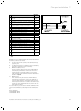

Electrical installation
Installation and maintenance instructions ecoTEC plus 0020116700_06 29
8
b
Caution.
Risk of damage caused by incorrect
installation.
A mains voltage at the incorrect plug termi-
nals on the ProE system can destroy the
electronics.
> Only connect the mains connection cable
to the terminals marked for the purpose.
b
Caution.
Risk of damage caused by incorrect
installation.
Connecting wires that have been stripped
too far can cause short circuits and damage
the electronics if a strand accidentally
comes loose.
> Only strip the outer sheathing of flexible
cables for a maximum of 3cm to prevent
short circuits.
> Lay the lines correctly.
> Use strain reliefs.
i
If you install the boiler in safety area 2, it can
only be operated if it is room sealed. Installation
method B53P is not permitted in this case.
Please pay attention to the latest edition of the
"IEE Wiring Regulations – BS7671, Requirements
for Electrical Installation".
In IE, reference should be made to the current edition of
the ETCI (Electro-Technical Council for Ireland) rules.
The boiler is supplied for connection to 230V, ~50Hz sup-
ply fused at 3A rating. Connection to the mains supply shall
be made via a fused 3 pin plug to an unswitched shuttered
socket, both complying with the requirements of BS1363.
(Alternatively, connection may be made via a 3 A fused
double pole isolator having a contact opening of at least
3mm in all poles and supplying the boiler and controllers
only). The point of connection to the mains supply must
allow complete electrical isolation of the boiler and its ancil-
lary controllers. It should be readily accessible and adjacent
to the boiler. A flexible cord fulfilling BS6500 or compara-
ble standard, conductor diameter between 0,75 and 1,5mm
2
and an allowed temperature range including 90°C should
be used.
The nominal voltage of the mains must be 230V; at mains
voltages greater than 253V and less than 190V the func-
tions may be impaired.
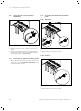
> Open the electronics box (¬section8.2).
> Use a normal commercial mains connection cable that is
compliant with standards.
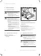
> Route the mains connection cable through the left cable
duct (¬fig. 8.1, pos.4) on the base of the unit.
1
3
2
8.2 Cable routing of the mains connection cable
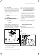
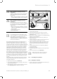
> Use the strain reliefs (1).
> Shorten the mains connection cable as necessary.
> Only strip the outer sheathing of flexible cables for a
maximum of 3cm.
> Ensure inner conductor insulation is not damaged during
stripping of outer sheathing.
> Only strip inner conductors sufficient to make good
sound connections.
> Crimp pin terminals to ensure a secure connection free
from loose strands to prevent short circuits.
> Take the turquoise ProE plug (2) for the mains connec-
tion out of the bracket in the electronics box and con-
nect the plug professionally to the mains connection
cable.
> Insert the ProE plug into the corresponding PCB slot
(L, N and earth) (3).
> Lay the lines correctly.
> Secure the cable in the electronics box using the strain
reliefs.
> Close the electronics box (¬section8.2).
i
Make sure that the connection cables are
securely fastened to the plug terminals.
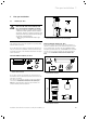
8.4 Connecting the controller
8.4.1 Fitting the controller
> Fit the controllers in accordance with the relevant oper-
ating and installation instructions.