
Technical data


Instructions for Use, Installation and Servicing ecoMAX pro 17
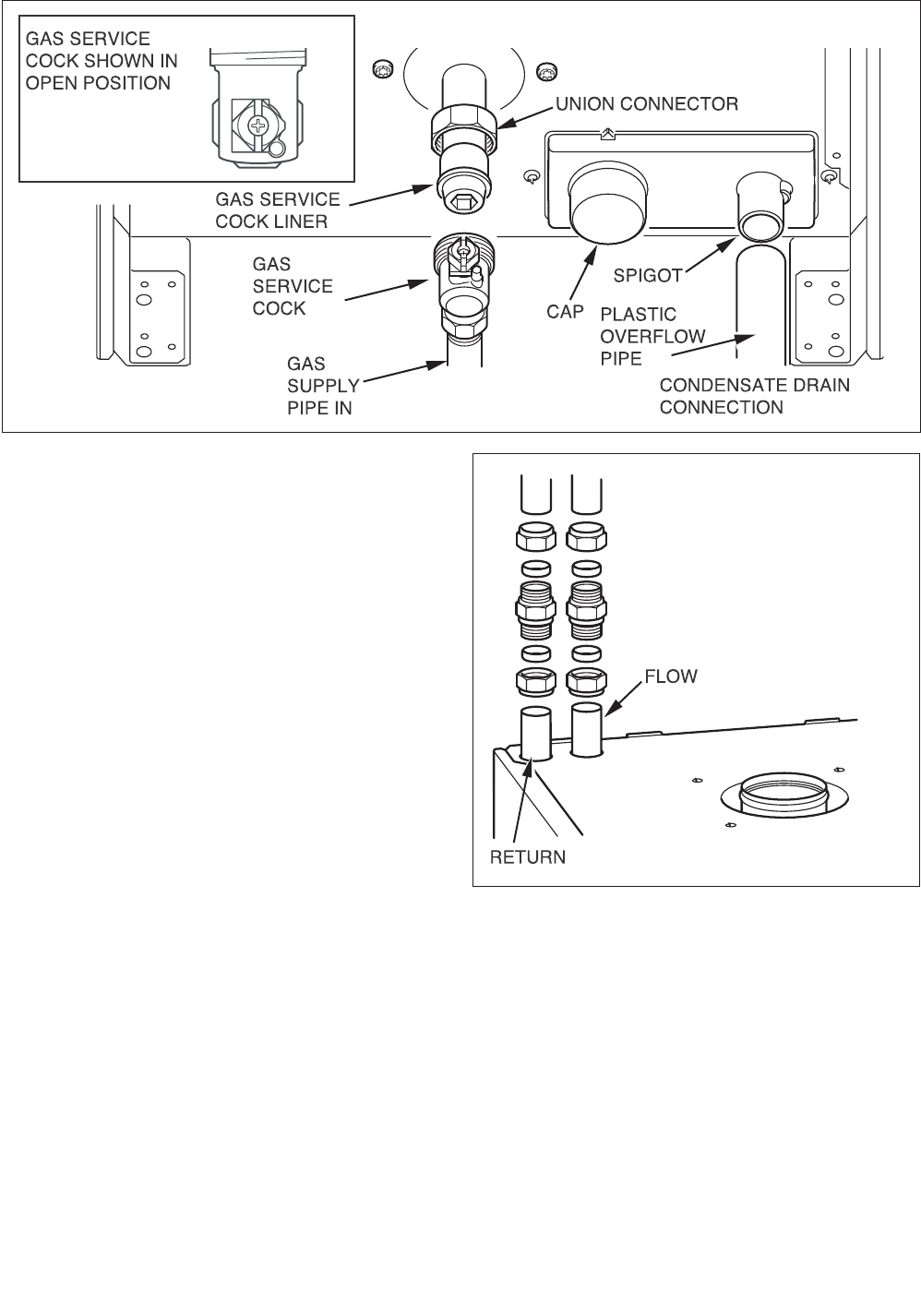
10 Gas, Water and Condensate connections
10.1 Gas Connection
Before connection check the supply of local gas.
The gas supply can be connected from below, or through
the wall at the rear of the boiler.
Ensure the supply pipe is fully engaged in the
compression fitting on the gas service valve inlet. See
Fig. 10.1. and refer to section 4.3.
10.2 Water Connections
Provision is made for the water connections to be made
from above the boiler, see Fig. 10.2 (using the two 22mm
compression couplers supplied). The position is shown
on the wall template.
Flush out the domestic hot water and the heating
systems before connecting to the boiler.
10.3 Condensate Drain Connection
The condensate drain connection is at the rear of the
boiler, see Fig. 10.1. A 21.5 mm plastic overflow pipe
should be connected to the spigot on the condense trap
(using the coupler). The drain pipe should have a fall of
a least 2.5° away from the boiler. Condensate should,
if possible be discharged into the household internal
drainage system. If this is not practicable, discharge
can be allowed into the external household drains or a
purpose designed soak away.
It is recommended that any external condensate drain
pipe is insulated and also preferably of 32mm diameter,
to prevent freezing in adverse weather conditions.
The condensate is discharged periodically in ‘slugs’ by
siphonic action.
It is not necessary to provide air breaks or extra traps
in the discharge pipe, as there is already a 75mm high
trap inside the boiler. Fitting an extra trap may cause
the boiler siphon to work incorrectly. Refer to BS 6798
and BS 5546 for advice on the disposal of the boiler
condensate.
Fig 10.2
12692
Fig 10.1
12691