
Technical data


Instructions for Use, Installation and Servicing ecoMAX pro16
8 Installation Preparation 9 Boiler fixing
8.3 Rear flue exit
Mark the position of the air/flue duct and its
circumference.
8.4 Other flue options
Flue instructions for other flue systems such as vertical
RSF flues, flues run to the side of the boiler and the use
of additional bends etc. are detailed in the flue
installation instructions.
Remove the template from the wall and plug the drilled
holes using the wallplugs supplied.
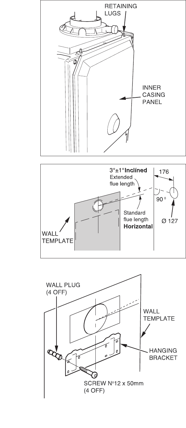
8.5 Flue Hole Cutting
The standard horizontal flue is designed with an internal
fall of 50 mm (
± 20 mm) /metre towards the boiler for
disposal of condensate.
If the standard flue length alone is being used then the
flue hole can be cut in the position marked on the wall
template.
For installations with external access, a 107 mm diameter
core drill can be used.
For installations with internal access only, a 127 mm
diameter core drill should be used.
For extended side flues, the flue hole centre should be
determined by extending the dashed incline line on the
template to the side wall. This dashed line is drawn at
a 50 mm/metre (3°) rise from the boiler. Where this line
reaches the side wall, a horizontal line should be marked.
The vertical centre line of the flue should then be marked
at 176 mm from the back wall, see Fig.
8.3.
To allow for the flue passing through the wall at this angle
a 127 mm hole should be drilled irrespective of internal
or external installation.
If necessary remove the template whilst drilling the flue
hole.
9 Boiler fixing
9.1 Fitting the boiler hanging bracket
Fix the hanging bracket to the wall using the screws
supplied. Ensure the uppermost set of screw positions
are used (it may be necessary to use additional or
alternative fixings to ensure adequate support).
NOTE:
If the boiler is to be fitted in a timber framed
building ensure that the bracket is secured to a
substantial part of the timber frame capable of
taking the weight of the boiler.
9.2 Boiler Fixing
Having previously secured the hanging bracket to the
wall, lift the boiler into position in the following manner:
Lean the top of the boiler slightly to the wall and
position just above the hanging bracket. Allow the boiler
to slowly move downwards until engaged in the hanging
bracket.
Fig 8.2
12688
Fig 8.3
12689