
Installation manual


Installing the 130 mm diameter system 6
0020058722_04 Air/flue gas system Installation manual 19
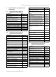
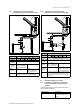
6.2 Installing the basic set for shaft installation
6.2.1 Basic set for the shaft installation, article
number 0020042762
500
Ø130
220
220
250
300
250
180
207
Ø125
1
4
5
2
3
8
7
6
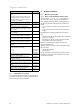
1 Shaft cover for PP, 130
mm (1 pc)
2 Spacer for PP, 130 mm (7
pcs)
3 Safety pipe for shaft open-
ing, DN 180, 300 mm
(1 pc)
4 Support elbow (PP) 130,
87° incl. mounting rail (1
pc)
5 Sealing tape
6 Flue pipe, aluminium (no
sleeve), 500 mm long
(1 pc)
7 Ventilation grille (1 pc)
8 Wall collar for PP 130
(1 pc)
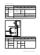
6.2.2 Preparing the installation
1. Determine the installation site of the flue gas guiding in
the shaft.
2. Drill a sufficiently large opening to allow enough space
for installation.
3. Drill a hole in the rear side of the shaft.
– Diameter: 10 mm
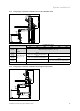
6.2.3 Installing the support elbow and inserting
the flue pipes in the shaft
002 .nim
1
2
3
4
5
1. Mortise a sufficiently large opening at the installation
site to allow enough space for installation.
2. Insert the support elbow with the mounting rail (5) so
that the flue pipe is positioned in the centre of the shaft.
3. Slide the spacer (3) onto the flue pipe.
– Distance between the spacers: ≤ 2 m
4. Use a line (2) to lower the first flue pipe (4) down far
enough until you can insert the next flue pipe (1).
– The sleeve side of the flue pipe must always point
upwards.
5. Continue joining the pipes together until you can insert
the lowest pipe into the support elbow.
6. If the flue gas pipe cannot be inspected from the shaft
opening, install an inspection T-piece in a suitable posi-
tion (article number 0020042764).
Conditions: Diversions required in the shaft
▶ Install a 15° or 30° elbow (article number 0020042768
and 0020042767).
7. After every diversion, install an inspection T-piece as
close as possible to the diversion.