
Installation manual


System conditions 5
0020058722_04 Air/flue gas system Installation manual 17
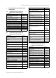
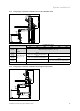
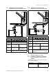
5.1.7 Flue gas pipe on the external wall,
combustion air from the installation room
L
3
L
1
L
2
min. 1m
ecoCRAFT VKK../3-E-HL
806
1206 1606 2006 2406 2806
System
Maximum total pipe length (L1 + L2 + L3)
130 mm
diameter
‒
160 mm
diameter
50.0 m
plus 1 x diversion 87°
plus support elbow
‒
200 mm
diameter
‒ 50.0 m
plus 1 x diversion 87°
plus support elbow
The horizontal flue gas pipe must have a max-
imum length of 10 m, minus the 87° diversion.
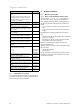
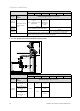
5.1.8 Flue gas pipe on the external wall,
combustion air through the external wall
L
4
L
1
L
2
L
3
min. 1m
ecoCRAFT VKK../3-E-HL
806
1206 1606 2006 2406 2806
System
Maximum total pipe length
(L1 + L2 + L3 + L4)
130 mm
diameter
‒
160 mm
diameter
50.0 m
plus 1 x diversion 87°
plus support elbow
‒
200 mm
diameter
‒
50.0 m
plus 1 x diversion 87°
plus support elbow
The horizontal lines must have a maximum length
of 20 m, minus the 87° diversion, of which max.
10 m is for the air pipe and max. 10 m is for the
flue gas pipe.
5.2 General installation instructions
5.2.1 Technical properties of the air/flue gas
systems from Vaillant for calorific value
products
The air/flue gas systems from Vaillant demonstrate the fol-
lowing performance features:
Technical feature Description
Temperature resistance Adapted to the maximum
flue gas temperature of the
product.