Installation manual For the competent person Installation manual Air/flue gas system VKK ..
Legal information Document type: Installation manual Product: Target group: Air/flue gas system – 130 mm diameter system – 160 mm diameter system – 200 mm diameter system Authorised competent person Language: EN Document number_version: 0020058722_04 Created on: 26.09.2012 Publisher/manufacturer Vaillant GmbH Berghauser Str. 40 D-42859 Remscheid Telefon +49 21 91 18‑0 Telefax +49 21 91 18‑28 10 info@vaillant.de www.vaillant.
Contents Contents 1 Notes on the documentation .............................. 4 1.1 Observing other applicable documents ................. 4 1.2 Storing documents................................................. 4 1.3 Applicability of the instructions .............................. 4 2 Safety .................................................................... 5 2.1 Action-related warnings ......................................... 5 2.2 Required personnel qualifications ........................
1 Notes on the documentation 1 1.1 Notes on the documentation Observing other applicable documents For the competent person: – 1.2 ▶ Installation instructions for the installed Vaillant product. Storing documents Pass these instructions and all other applicable documents on to the system operator. The system operator should retain these instructions for further use. 1.
Safety 2 2 Safety 2.
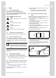
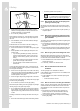
2 Safety – Note 3° corresponds to a downward gradient of approx. 50 mm per metre of pipe length. 1 2.3.4 2 ▶ ▶ When fitting the flue pipes, make absolutely sure the seals are correctly positioned. The lip of the seal must be facing inwards (1), not outwards (2). Do not use any damaged seals. Mortar residues, shavings, etc. in the flue pipe may restrict the outward flow of the flue gas. Flue gas may escape into the room. ▶ After installation, remove all mortar residues, shavings, etc.
Safety 2 2.3.9 Inspect/clean chimneys to which former solid fuel boilers were once connected We recommend that you have chimneys inspected and cleaned by a chimney sweep before the flue gas pipe is installed if these chimneys were previously used to divert flue gas away from solid-fuel-fired boilers but should now supply combustion air. If it is not possible to adequately inspect/clean the chimney (e. g. due to construction features), you can – – 2.3.
2 Safety This installation manual is a component of the certification and is cited in the type testing certificate. In compliance with the regulatory statutes of this installation manual, the proof of usability of the products identified by Vaillant article numbers that are designed for the flue pipe is provided. If you do not use certified elements for the Vaillant flue pipe when installing the products, this voids the CE conformity of the product.
System overview 3 3 System overview 3.2.3 Flue gas pipe in the shaft, combustion air from the shaft Observe the maximum pipe lengths, see "Maximum pipe lengths" (→ Page 12). 3.1 Combination options for systems with VKK 130 mm diameter 160 mm diameter 200 mm diameter VKK 806/3-E-HL VKK 1206/3-E-HL VKK 1606/3-E-HL VKK 806/3-E-HL VKK 1206/3-E-HL VKK 1606/3-E-HL VKK 2006/3-E-HL VKK 2406/3-E-HL VKK 2806/3-E-HL 3.2 130 mm diameter system 3.2.
3 System overview 3.3.3 Flue gas pipe in the shaft, combustion air from the shaft ▶ Flue gas connection and installing the horizontal flue gas pipe (→ Page 31) 3.3.6 ▶ ▶ ▶ Installing the flue gas pipe in the shaft (→ Page 22) Installing the combustion air line in the shaft (→ Page 31) Flue gas connection and installing the horizontal flue gas pipe (→ Page 31) 3.3.4 Flue gas pipe through the roof, combustion air from the installation room 1.
Certified air/flue gas systems and components 4 4 4.1 Certified air/flue gas systems and components Certified air/flue gas systems and components, 130 mm diameter Components Art. no. Flat roof penetration collar (aluminium), for the roof duct, 160/186 mm diameter 0020095570 External wall connection (stainless steel), elbow, support console, external collar, 160/225 mm diameter 0020095573 Components Art. no.
5 System conditions Components Art. no. Spacer (stainless steel), 1 pc, 200 mm diameter Note: The spacer is bent in its film packaging. In the as-delivered condition, the struts are straight. The spacers must be put back into their round shape before the installation.
System conditions 5 Flue gas pipe in the shaft, combustion air from the installation room L3 m in .1 m 5.1.2 L2 L1 ecoCRAFT VKK../3-E-HL 806 1206 Shaft cross-section: At least System 130 mm diameter 160 mm diameter 200 mm diameter Round: DN + 60 mm Angular: DN + 40 mm 1606 2006 2406 2806 Maximum total pipe length (L1 + L2 + L3) 33.0 m plus 3 x 87° diversions and support elbow ‒ 50.0 m plus 3 x 87° diversions and support elbow ‒ ‒ 50.
5 System conditions ecoCRAFT VKK../3-E-HL 806 System 130 mm diameter 160 mm diameter Shaft cross-section: At least 1206 1606 2006 2406 2806 Maximum total pipe length (L1 + L2 + L3 + L4) 40.0 m plus 1 x diversion 87° and support elbow Round: DN + 60 mm Angular: DN + 40 mm 38.0 m plus 1 x diversion 87° and support elbow ‒ 50.0 m plus 1 x diversion 87° and support elbow ‒ ‒ 50.
System conditions 5 ecoCRAFT VKK../3-E-HL 806 System 130 mm diameter 1206 Shaft cross-section: At least 1606 2006 2406 2806 Maximum total pipe length (L1 + L2 + L3) Round: DN + 120 mm Angular: DN + 100 mm 35.0 m 35.0 m Round: DN + 70 mm Angular: DN + 40 mm ‒ 35.0 m 39.8 m Round: DN + 90 mm Angular: DN + 60 mm 160 mm diameter Round: DN + 120 mm Angular: DN + 80 mm 50 m ‒ 50 m 50 m Round: DN + 140 mm Angular: DN + 100 mm Round: DN + 70 mm Angular: DN + 40 mm 38.
5 System conditions Flue gas pipe through the roof, combustion air from the installation room 5.1.6 Flue gas pipe through the roof, combustion air through the external wall L3 L3 m m in in . . 1m 1m 5.1.5 L2 L1 L2 L1 L4 ecoCRAFT VKK../3-E-HL 806 ecoCRAFT VKK../3-E-HL 806 1206 1606 2006 2406 2806 System Maximum total pipe length (L1 + L2 + L3) 130 mm diameter ‒ 160 mm diameter 200 mm diameter 25.0 m plus 3 diversions 87° ‒ ‒ 25.
System conditions 5 Flue gas pipe on the external wall, combustion air from the installation room 5.1.8 Flue gas pipe on the external wall, combustion air through the external wall L3 L3 m m in. 1m in .1 m 5.1.7 L2 L1 L1 L2 L4 ecoCRAFT VKK../3-E-HL 806 ecoCRAFT VKK../3-E-HL 806 1206 1606 2006 2406 2806 System Maximum total pipe length (L1 + L2 + L3) 130 mm diameter ‒ 160 mm diameter 200 mm diameter 50.0 m plus 1 x diversion 87° plus support elbow ‒ ‒ 50.
6 Installing the 130 mm diameter system Technical feature Description Leaks Adapted to the product for use in buildings and outdoors Condensate resistance For gas and oil fuels Corrosion resistance Adapted to the gas and oil condensing boiler Clearance from combustible materials Not necessary Installation location In accordance with the installation instructions Resistance to fire Normal level of flame resistance (in accordance with EN 13501-1 Class E) Fire resistance time None: The external
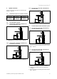
Installing the 130 mm diameter system 6 6.2 Installing the basic set for shaft installation 6.2.1 Basic set for the shaft installation, article number 0020042762 Installing the support elbow and inserting the flue pipes in the shaft Ø125 220 8 6.2.3 207 220 1 2 250 7 3 250 1 2 300 4 180 Ø130 3 m in . 20 0 500 6 5 4 5 1 2 3 4 Shaft cover for PP, 130 mm (1 pc) Spacer for PP, 130 mm (7 pcs) Safety pipe for shaft opening, DN 180, 300 mm (1 pc) Support elbow (PP) 130, 87° incl.
6 Installing the 130 mm diameter system 6.2.4 Installing the shaft extension 5. Fit the wall collar (4) that is contained within the scope of delivery over the flue pipe. Only secure the wall collar to the shaft after completing the installation work. Create an opening at the foot of the shaft for rear ventilation of the shaft. 1 min. min. 100 mm 300 mm 2 1. 2. 3. 4. 5. 6. Conditions: Rear ventilation of the shaft required 3 4 – Dimensions: 150 x 150 mm Secure the ventilation grille (3).
Installing the 130 mm diameter system 6 6.3.2 Install the flue gas connection on the boiler 2 1 3 1 1. 2. 3. Insert the extension with measurement opening (1) into the product's condensate trap. Insert the 87° elbow (2) into the extension. Insert the transition piece at 130 mm (3) into the 87° elbow. – Always incorporate the diameter reduction from 150 to 130 mm in the horizontal flue gas pipe. 6.3.3 1. 2. After each 45° diversion, install an extra clamp (1) to the extension. 6.
7 Installing the 160 mm diameter and 200 mm diameter systems 2. 3. 4. 5. 6. 7. – Diameter: 130 mm Place the wall panel (1a) on the air pipe (a). Insert the air pipe (2) into the opening (b) so that the air pipe (2) and the wall panel (1b) are flush with the wall. – The sleeve must point to the boiler. Secure the air pipe (2) with mortar and leave the mortar to harden. Install the 130 mm diameter collar to the inside.
Installing the 160 mm diameter and 200 mm diameter systems 7 7.1.1 Scope of delivery of the basic set for the shaft installation, article number 0020095533 (160 mm diameter), 0020095534 (200 mm diameter) 7.1.3 Installing the support elbow 7 6 1 200 240 x 230 6 500 5 5 4 230 ( 300) Ø 160 (Ø 200) 3 400 ( 500) Ø 160 (Ø 200) 151 min. 250 mm Ø 225 (Ø 300) 4 2 3 2 Ø 350 1 2 3 Shaft cover Flue pipe (PP), black (no sleeve), 500 mm long Support elbow (PP) 130, 87° incl.
7 Installing the 160 mm diameter and 200 mm diameter systems 7.1.5 1. 2. 3. 4. 5. 6. 7. Inserting the flue pipes in the shaft Install the installation aid (4) to the lower end of the first flue pipe (3), see section Installing the support elbow (→ Page 23). – The sleeve side of the flue pipe must point upwards Use a snap hook to secure the line to the installation aid. – The installation aid may have sharp edges and cut through the line.
Installing the 160 mm diameter and 200 mm diameter systems 7 7.1.8 Installing the flue pipe, safety pipe, wall panel and ventilation grille 3 2 1 1 1. 2. 3 Saw through the flue gas pipe (1) at the marking (2). Turn the sawn-off sleeve (3) around and slide it back onto the flue pipe. 4 2 1. 2. 3. Insert a 500 mm flue pipe (1) into the support elbow. Insert the wall chuck for the shaft opening (2) into the borehole. Secure the wall chuck with mortar and leave the mortar to harden.
7 Installing the 160 mm diameter and 200 mm diameter systems 7.3.2 Installing the roof duct 7.4 Installing the flue gas pipe on the external wall System diagram 1 1 2 2 3 3 5 4 4 5 6 1. 2. 3. Insert the vertical roof duct (1) into the pitched roof tile (2) or the flat roof penetration collar from above. Align the roof duct vertically and secure the clamp (3) to a rafter or the ceiling. Install the extensions (4) and, if necessary, the inspection openings (5). 7.3.
Installing the 160 mm diameter and 200 mm diameter systems 7 Static dimensions of the flue gas pipe 7.4.2 Static dimensions for an offset of the flue gas guiding D A C 1 Max. 5 m A A 2 B 1 2 A Max. 4 m A Max. 50 m (max. vertical height above the support console) B Max. 2 m (distance between the pipe brackets) C Max. 2 m (distance between the two upper pipe brackets) D Max. 1.5 m (max. height above the last pipe bracket) ▶ ▶ ▶ ▶ Danger! Risk of injury due to falling parts.
7 Installing the 160 mm diameter and 200 mm diameter systems 7.4.4 Assembling and installing the support console 7.4.5 Installing the connection for the external wall pipe 3 1 2 7 1 6 1 a) 1. 2. 3. 4. 3 2 Fit the support console to the external wall. Set the wall distances as follows: – 160/225 system: 160 mm – 200/300 system: 220 mm The support console and pipe bracket thus have an adjustment range of +/- 20 m. Tighten all screws on the pre-assembled support console.
Installing the 160 mm diameter and 200 mm diameter systems 7 – 7.4.7 3 External wall element 5 Seam 4 Safety screws 6 Seam 1. Adjustment range of the pipe brackets 24 Ø2 99) 2 (Ø 43-81 (51-89) Install the flue gas pipes, the terminal and, if necessary, the inspection opening and diversions. – Distance between the opening and the roof area: ≥1m – For vertical installation, clamps are only required when using offsets or in specific opening situations.
7 Installing the 160 mm diameter and 200 mm diameter systems 7.4.10 Shortening the roof duct 3. Connect this pipe bracket to the roof construction using struts (4) or rope. 1 7.5.1 Shortening the extension 2 3 1 4 5 2 1 Roof duct 2 Fastening clamp 3 External pipe of the roof duct 1. 4 5 Internal pipe of the roof duct Connecting sleeve Pull the connecting sleeve (5) from the external pipe (3). Shorten the external pipe (3) and the internal pipe by an equal distance (maximum 20 cm).
Installing the 160 mm diameter and 200 mm diameter systems 7 ▶ ▶ To prevent this risk, follow the instructions below. Do not install this extension in the area in which additional clamps should be attached; or install an additional wall bracket (1) so that the system cannot become loosened and separated by wind load. Install an additional wall bracket directly above the shortened extension (1). ▶ 7.6 7.7 Installing the combustion air line 7.7.1 Installing the combustion air line in the shaft 1.
8 Customer service 1 2 2. 3. 4. 5. 6. 7. 3 4 5 6 7 Create a borehole. Place the 130/160 mm diameter air pipe adapter (3) on the air supports (2) of the boiler. If required, install an inspection opening (4). Insert further pipe elements. Before inserting the last pipe, slide the internal collar onto this pipe. Insert the last pipe (5) into the shaft opening (6) in such a way that the outer end is flush with the external wall (7).
Index Index A Air pipe ................................................................................ 22 Aluminium pipe.................................................................... 20 C Combustion air line Installing in the external wall.......................................... 31 Combustion air line 130 mm diameter system: Installing in the external wall................................................................................. 22 130 mm diameter system: Installing in the shaft ...........
0020058722_04 Vaillant Ltd Nottingham Road Belper Derbyshire DE56 1JT Telephone +44 845 602 29 22 Vaillant Service Solutions +44 80 70 606 07 77 info@vaillant.co.uk www.vaillant.co.