Wireless Security System 2GIG-CNTRL2 Installation & Programming Instructions Technical Support 866-670-1591 www.2gig.
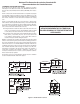
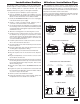
National Fire Protection Association Standard #72 Recommendations for Smoke Detectors STANDARD FOR ALARM LOCATION Smoke detectors used with this system should be installed in accordance with Chapter 2 of the National Fire Alarm Code, ANSI/NFPA 72 (National Fire Protection Association, Batterymarch Park, Quincy, MA 02269) which reads as follows: 2-1.1.
Table of Contents Introduction................................................................................ 2 System Overview ....................................................................... 3 Programming Outline .............................................................. 16 SIA CP01 Defaults ............................................................... 16 Control Panel Features ............................................................. 4 Programming Question Table .....................
Introduction The Go!Control Security System represents a significant advancement in fully supervised wireless security systems. The security system Control Panel incorporates many advanced and sophisticated features. The system can be expanded and customized to fit the installation’s specific needs. Designed to meet or exceed the requirements for ETL Listed residential security installations, the system also conforms to the Security Industry Association’s Control Panel Standard ANSI/SIA CP-01-2007.
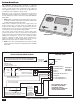
System Overview The system’s Control Panel features a color touch screen display that allows control of all system functions and programming. The display clearly shows the installer and subscriber system and installation status. The helpful scrolling text, along with the voice prompts that the Control Panel sounds, make installation, programming, and operation very easy compared to keypad-programmed and operated security systems of the past.
Control Panel Features ALARM SOUNDER AND SPEAKER COLOR DISPLAY WITH TOUCH SCREEN 2GIG-CNTRL2 Sounds all system local alarms, voice prompts, system sounds, and audio for 2-way voice communications with the Central Station Shows all system information, status, programming, and functions as the keypad.
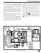
Installation Outline Wireless Installation Tips The following outline is intended to guide the installing alarm dealer through the complete installation of a Go!Control system. When installing any wireless system, certain limitations must be considered. Low power wireless transmitter signals will not broadcast equally through all types of construction materials. The Control Panel contains a very sensitive receiver that should allow placement of transmitters in almost all locations.
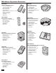
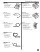
Wireless System Sensors 2GIG-DW10 Thin Door/Window Contact • For narrow applications, sensor is only 3/4” wide • Fully supervised • Rare earth magnet • Lithium battery • Supports internal and external contacts • Can be used for two zones of protection • 345 MHz • ETL Listed 2GIG-DW20R Recessed Door Contact • • • • • • Compact size, only 2-1/2” long Fully supervised Rare earth magnet Lithium battery 345 MHz ETL Listed 2GIG-PIR1 Passive Infrared Motion Detector • Dual element sensor with 50’ by 50’ range •
System Accessories 2GIG-GSMx GSM Module • Cellular telephone module • Plugs into Control Panel • Provides 2-way GSM radio communication • Enrolls with cellular service provider 2GIG-ANT1 Internal GSM Antenna • Antenna installs inside Control Panel • Plugs into GSM module • Small size • Locking connector 2GIG-ANT1X External In-wall GSM Antenna • Antenna installs in the wall behind Control Panel • 2-foot cable • Plugs into GSM module • Locking connector 2GIG-BATT1 Standard Battery Pack • Standard battery s
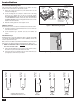
Installation Control Panel Mounting Plate The Control Panel should be mounted on the wall in an easy location for the subscriber to operate the system. IF USING EXTERNAL GSM ANTENNA, REMOVE KNOCKOUT MOUNTING PLATE 1. Remove the locking screw from the top of the Control Panel case and remove the mounting plate. MOUNT PLATE WITH 3 SCREWS 2. Use the mounting plate as a template to mark the wall for the wiring cutout slot. Use a drywall saw to cut the slot.
Installation Remote Alarm Sounder The Control Panel provides two terminals for an optional connection to a remote electronic alarm sounder. DO NOT CONNECT AN ELECTROMECHANICAL BELL TO THESE TERMINALS. The bell terminals can be supervised. If bell trouble reporting is enabled and the wire between the Control Panel and sounder is cut, the Control Panel will report bell trouble. 1. Install the remote sounder in a secure location where it can easily be heard. 2.
Installation Optional GSM Module Installation 1 If using the optional GSM module and one of the GSM antennas. Refer to the following steps: 1. Plug the GSM module into the connector on the Control Panel’s circuit board. Secure it with the two screws. 2A. If using the Model 2GIG-ANT1 internal antenna, remove the antenna access cover. Route the antenna lead through the opening in the case and place the flat antenna into the slot.
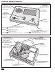
Installation Control Panel Wiring The Control Panel includes a “third hand” plastic strap that allows the unit to hang on the mounting plate during installation. 1. Hang the Control Panel on the mounting plate using the “third hand” strap (see Figure 16). 2. Connect the hardwire loop, external sounder, and open collector output wiring (if used ) to the Control Panel’s terminal block.
Main Display Screens The Control Panel is programmed and operated using the color touch-screen display. The display will show various buttons, indicators, and text to guide the installer and user. Home Screen The Home Screen is the top level screen. It shows the system status with icons to indicate system conditions. It also displays the time and date. System information scrolls along the top of the display. The Home Screen displays the SECURITY and HOME SERVICES buttons.
Toolbox Screens The Control Panel is programmed using the “toolbox” screens. Users can access basic programming functions. Installers can access basic and Installer Toolbox functions. Users and installers must enter a valid code to access the programming functions in the toolbox. Other functions do not require entering a code. Toolbox Screens From the Menu Screen, pressing the TOOLBOX button displays the Toolbox Screen one. The arrow button displays Toolbox Screens two and three.
System Status Icons The top line of the Control Panel’s display is the status bar that shows the current system mode, the status of the sensors, and any current system trouble alerts. Special icons are displayed to visually show the system’s current condition. STATUS BAR SHOWING AC POWER IS ON Figure 31. System Status Bar AC Power Icon The AC power icon indicates the Control Panel’s AC line power status.
Programming Navigation When the installer is using the System Configuration menus, the Control Panel will present each programming question sequentially. Most programming questions have a single numeric value response or a simple enabled/disabled selection. Some programming questions have sub-options that can be set. These sub-options are displayed for the question selected and can be accessed through navigation keys on the display.
Programming Outline Each system installed will require programming. Most installations being performed by the professional alarm installer for a specific organization will have common values set in every Control Panel reporting to the same Central Station. Other programming values, such as the account number and sensor setup, will be unique for each installation. Following is an outline to guide the professional alarm installer through the programming of the Control Panel.
Programming Question Table Q# Q-1 SUB-QUESTIONS Q-1 Q-2 SUB-QUESTIONS Q-2 Q-3 SUB-QUESTIONS Q-3 Q-4 SUB-QUESTIONS Q-4 QUESTION DEFAULT Q# QUESTION DEFAULT Q-24 Select radio modem network failure causes trouble (0-1) (1) enabled Select RF sensor # (01-48) Select RF sensor (#) type (00) unused Q-25 Select radio modem network failure reports (0-1) (1) enabled Select RF sensor (#) equipment type Varies by RF sensor type (Only shown for some sensor types) Q-26 Select auto stay (0-1) ‡ (1) e
System Sensor Types Each sensor (wireless or wired) installed in the system is programmed to a specific sensor number and sensor type (zone). The sensor number identifies the specific sensor when it is displayed on the Control Panel, recorded in the event log, or reported to the Central Station. This allows pin-point information about any sensor in the system. The sensor type determines how and when the Control Panel responds to signals from the sensor.
System Vocabulary Table # WORD # WORD # WORD # WORD 002 ABORT 066 ELEVEN 130 LIGHT 194 SET 003 AC 067 EMERGENCY 131 LIGHTS 195 SEVEN 004 ACCESS 068 ENTER 132 LIQUOR 196 SEVENTEEN 005 ALARM 069 ENTRANCE 133 LIVING 197 SEVENTY 006 AND 070 ENTRY 134 LOADING 198 SHED 007 ANNOUNCEMENT 071 ERROR 135 LOCK 199 SHOP 008 AREA 072 EXERCISE 136 LOFT 200 SIDE 009 ARM 073 EXIT 137 LOW 201 SILENT 010 ARMED 074 EXIT NOW 138 MAIN 202 SIREN 011
Installer Programming RF Sensor Programming RF Sensor Programming Outline The Control Panel can be programmed with up to 48 RF sensors of different types. In addition to the 48 multi-purpose RF sensors, eight RF remote control key fobs and four RF remote control keypads can be programmed into the system. Refer to Figure 48 for an outline of the steps required to program RF sensors into the Control Panel.
Installer Programming RF SENSOR PROGRAMMING (Q-1) OUTLINE STEP DOWN THROUGH OPTIONS SELECT OPTION WITH THESE KEYS ENTER ON KEYPAD OR PRESS SELECT RF SENSOR # PRESS FOR NEXT OPTION PRESS TO SELECT FROM LIST OR PRESS SKIP TO JUMP TO Q-2 ENTER ON KEYPAD OR PRESS ENTER ON KEYPAD OR PRESS OR TO SELECT FROM LIST FOR NEXT OPTION ENTER ON KEYPAD OR PRESS OR ENTER ON KEYPAD FOR NEXT OPTION ENTER ON KEYPAD OR PRESS ENTER RF SENSOR SERIAL NUMBER PRESS FOR NEXT OPTION shift OR TO SELECT FROM LIST FOR
Installer Programming RF Sensor Programming Steps Q-1 Select RF sensor # (01-48) Up to 48 wireless RF sensors can be used with each Control Panel. The options for each sensor are programmed with sub-option questions. • Begin by entering the RF sensor number or select it using the ← or → arrows. • After selecting the sensor number, program the sensor details by using the ↑ and ↓ arrows to select each of the sub-options.
Installer Programming Enter RF sensor (#) serial number (7 digits) DEFAULT: 0000000 Construct RF sensor (#) voice descriptor DEFAULT: No default RF sensor serial numbers can be manually entered or learned from the sensor. The voice descriptors are the words the Control Panel will announce for this RF sensor if this sensor is programmed for voice annunciation. Up to five words are allowed. • For manual entry, enter the sensor number that was logged for the sensor being programmed.
Installer Programming Wired Sensor Programming Wired Sensor Programming Outline The Control Panel can be programmed with up to two wired sensors. The wired sensors are hardwired contact loops connected to the loop input terminals on the Control Panel’s terminal strip.
Installer Programming Wired Sensor Programming Steps Q-2 Select wired sensor # (1-2) Two hardwired loops can be used as sensors with each Control Panel. The options for each wired sensor are programmed with sub-option questions. • Begin by entering the wired sensor number or select it using the ← or → arrows. • After selecting the wired sensor number, program the wired sensor details by using the ↑ and ↓ arrows to select each of the sub-options.
Installer Programming RF Key Fob Programming KEY FOB PROGRAMMING (Q-3) OUTLINE STEP DOWN THROUGH OPTIONS RF Key Fob Programming Outline SELECT OPTION WITH THESE KEYS The Control Panel can be programmed with up to eight RF remote control key fobs. Programming the RF key fobs into the Control Panel involves selecting the sensor number for a particular device, setting or learning the RF key fob’s serial number, and selecting the other options for the sensor.
Installer Programming RF Key Fob Programming Steps Q-3 Select fob # (1-8) Up to eight wireless 4-button key fobs can be used with each Control Panel. Key fobs reports as sensors 51-58. The options for each fob are programmed with sub-option questions. Select fob (#) emergency key (0-4) DEFAULT: Disabled (0) Pressing the and buttons on a key fob at the same time for five seconds can trigger an emergency alarm. • The default (0) disables the emergency function for this fob.
Installer Programming RF Keypad Programming RF Keypad Programming Outline The Control Panel can be programmed with up to four RF remote control keypads. Programming the RF remote control keypads into the Control Panel involves selecting the sensor number for a particular device, setting or learning the RF remote control keypad’s serial number, and selecting the other options for the RF remote control keypad. • RF keypads #1 - #4 report as system sensors #59 - #62 for emergency, and low battery reports.
Installer Programming RF Keypad Programming Steps Q-4 Select RF keypad # (1-4) Up to four wireless keypads can be used with each Control Panel. The options for each sensor are programmed with sub-option questions. • Begin by entering the RF keypad number or select it using the ← or → arrows. • Program the RF keypads by using the ↑ and ↓ arrows to select the sub-options. ✓ NOTE: To skip RF keypad programming, press SKIP to jump from question Q-4 to question Q-5 (Exit Delay programming).
Installer Programming Control Panel Programming Questions Q-5 Enter exit delay, in seconds (45-120) DEFAULT: 60 seconds (Required SIA CP01 Default) The Exit Delay can be set from 45 to 120 seconds. • The default (60) sets the Exit Delay to 60 seconds. • To change the Exit Delay, enter a value from (45-120) seconds. ✓ NOTE: This default can be changed without affecting SIA CP01 compliance.
Installer Programming Q-15 Q-21 Select dialing type (0-1) DEFAULT: Touch tone (0) Select siren supervision time (0-3) DEFAULT: Disabled (0) The digital communicator can dial using tones or pulse. The wiring connection to the external sounder can be supervised. If the wiring to the sounder is cut for 15, 30, or 45 seconds, a bell trouble report can be sent to the Central Station. • The default (0) is for touch tone (DTMF) dialing. • For rotary dialing, select pulse (1).
Installer Programming Q-27 Q-33 Select exit delay restart (0-1) DEFAULT: Enabled (1) (Required SIA CP01 Default) Select cross sensor 47-48 (0-1) DEFAULT: Disabled (0) When Exit Delay restart is enabled, re-entering the premises through an exit/ entry door during the Exit Delay will restart the Exit Delay. The restart of the Exit Delay will only occur one time; further violations of an exit/entry sensor will not extend the Exit Delay.
Installer Programming Q-37 Q-42 Select fire bell cutoff (0-4) DEFAULT: 4 minutes (0) Select remote control phone (0-3) DEFAULT: Data and voice (3) When a fire alarm is triggered, the bell will sound until the fire bell cutoff time expires. This setting controls remote telephone access to the system. • The default (0) sets the fire bell cutoff time to 4 minutes.
Installer Programming Q-44 Q-47 Select lock installer programming (0-2) DEFAULT: Disabled (0) Select trouble resound after holdoff (0-7) DEFAULT: Disabled (0) The installer programming lockout feature is provided to prevent takeovers. The Control Panel can be set to limit an installer’s access to programming questions after a period of 48 hours. The 48 hour lockout timer starts when the installer exits system configuration mode.
Installer Programming Q-52 Q-58 Select AC loss reports to CS (0-1) DEFAULT: Enabled (1) Select trouble restore reports to CS (0-1) DEFAULT: Enabled (1) AC power loss reports can be sent to the Central Station if the Control Panel loses AC power. Trouble restore reports can be sent to the Central Station when any sensor trouble condition clears. • The default (1) allows AC power loss reports. • To turn off AC power loss reports, select disabled (0).
Installer Programming Q-64 Q-71 Select smart test reports DEFAULT: Disabled (0) Select system tamper causes trouble (0-1) DEFAULT: Enabled (1) Smart test reports are a way to reduce Central Station traffic. If smart test reports are enabled and regular periodic test reports are enabled, any non-test report to the Central Station (alarm, restore, trouble, etc.) during the normal operation of the system will reset the periodic test report timer.
Installer Programming Q-76 Q-79 Select force bypass reports (0-1) DEFAULT: Disabled (0) Select Z-Wave feature (0-3) DEFAULT: Disabled but visible (1) The system can report which sensors have been force bypassed by the user when the system is armed. Forced bypassed sensors are always recorded in the event log, regardless of the setting of this programming question. The Z-Wave home services feature can be enabled or disabled with various remote control access options.
Final Installation Setup Exiting Programming After programming the Control Panel, all the changes need to be saved in memory. After saving, the programmed settings will remain in memory, even after a total power loss. 4. Press BRIGHTNESS / VOLUME. Set the level for the display brightness. Set the chime & voice volume. Press OK when finished. 1. After setting all the required programming values for the sensors and the Control Panel, press END. 2. Review the Control Panel Summary screen.
Installer Testing Testing the System After the installation is complete and the Control Panel programming is complete, the system must be tested to ensure proper operation. System testing is performed through the Installer Toolbox screen. 1. From the Home Screen, press SECURITY, MENU, then TOOLBOX to access the Toolbox Screen. 2. Press the → arrow to go to the Toolbox Screen 2 of 3, then press INSTALLER TOOLBOX. Figure 63. Installer Toolbox 3.
Installer Testing Walk Test Mode Walk Test Mode is for testing all the sensors. It verifies that each sensor is being received correctly by the Control Panel. The walk test also tests the Control Panel’s indicators and sounder. ✓ NOTE: The Walk Test Mode will automatically end after 25 minutes. Signal Strength Indicators An important feature is the received signal strength indicators displayed by the Control Panel for each of the sensors.
Installer Testing Radio Status Mode ✓ NOTE: GSM Module must be installed to use this function. The GSM Radio Status screen displays data for the GSM radio (if installed). The screen displays signal strength, serial number, registration status, and other information about the GSM radio module status. The information may be helpful for radio installation troubleshooting. Follow these steps to check the radio status: 1. From the Installer Toolbox screen, press the RADIO STATUS button. Figure 71.
Installer Testing Restoring Programming Defaults To soft reset the Control Panel back to the factory defaults, use the Restore Default option in the Installer toolbox. ✓ NOTE: The Control Panel may also be “hard” reset to out-of-the-box factory defaults by pressing and holding the emergency and home buttons while applying power (if not disabled through programming questions Q-44 & Q-45).
Regulatory Information & Limited Warranty Wireless Product Notice Industry Canada Notices Radio controls provide a reliable communications link and fill an important need in portable wireless signaling; however, there are some limitations which must be observed. NOTICE: The ringer equivalence number (REN) assigned to each terminal device provides an indication of the maximum number of terminals allowed to be connected to a telephone interface.
Reference Programming Question Table Q# Q-1 SUB-QUESTIONS Q-1 Q-2 SUB-QUESTIONS Q-2 Q-3 SUB-QUESTIONS Q-3 Q-4 SUB-QUESTIONS Q-4 QUESTION DEFAULT Q# QUESTION DEFAULT Q-24 Select radio modem network failure causes trouble (0-1) (1) enabled Select RF sensor # (01-48) Select RF sensor (#) type (00) unused Q-25 Select radio modem network failure reports (0-1) (1) enabled Select RF sensor (#) equipment type Varies by RF sensor type (Only shown for some sensor types) Q-26 Select auto stay (0-1
Reference System Vocabulary Table # WORD # WORD # WORD # WORD 002 ABORT 066 ELEVEN 130 LIGHT 194 SET 003 AC 067 EMERGENCY 131 LIGHTS 195 SEVEN 004 ACCESS 068 ENTER 132 LIQUOR 196 SEVENTEEN 005 ALARM 069 ENTRANCE 133 LIVING 197 SEVENTY 006 AND 070 ENTRY 134 LOADING 198 SHED 007 ANNOUNCEMENT 071 ERROR 135 LOCK 199 SHOP 008 AREA 072 EXERCISE 136 LOFT 200 SIDE 009 ARM 073 EXIT 137 LOW 201 SILENT 010 ARMED 074 EXIT NOW 138 MAIN 202 SI
Notes _____________________________________________________________________ _____________________________________________________________________ _____________________________________________________________________ _____________________________________________________________________ _____________________________________________________________________ _____________________________________________________________________ _____________________________________________________________________ ________________
Notes _____________________________________________________________________ _____________________________________________________________________ _____________________________________________________________________ _____________________________________________________________________ _____________________________________________________________________ _____________________________________________________________________ _____________________________________________________________________ ________________
Index #’s 2GIG-AC1 replacement power supply 7 2GIG-ANT1 internal GSM antenna 7 2GIG-ANT1X external in-wall GSM antenna 7 2GIG-ANT2X external attic mount GSM antenna 7 2GIG-ANT4X 7 2GIG-BATT1 standard battery pack 7 2GIG-BATT1X extended battery pack 7 2GIG-DW10 thin door/window contact 6 2GIG-DW20R recessed door contact 6 2GIG-GB1 glass break detector 6 2GIG-GSMx GSM module 7 2GIG-KEY1 4-button key ring remote 6 2GIG-PANIC1 panic button remote 6 2GIG-PIR1 passive infrared motion detector 6 2GIG-SMKT2 smoke a
Index N S Navigation arrows 15 NFPA Standard #72 2 No response sensor type 18 Saving programming 38 Security screen 12 Sensor signal loss through materials 5 Sensor types 18 Sensor zones 18 Set date / time 38 SHIFT button 15 Signal strength indicators 40 Silent burglary sensor type 18 Silent panic/burglary listen only 30 Siren supervision time 31 SKIP button 15 Smart test reports 36 Smoke and heat detector 6 Smoke detector location 2 Solid state output 9 Sounder disable/enable 39 Sounder disable icon 14 S
Technical Support 866-670-1591 www.2gig.