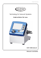
page 1 of 74 Technology for Vacuum Systems Instructions for use CVC 3000 detect Vacuum controller
page 2 of 74 Dear customer, Your VACUUBRAND controllers are designed to provide you with many years of trouble-free service with optimal performance. Our many years of practical experience allow us to provide a wealth of application and safety information. Please read these instructions for use before the initial operation of your controller.
page 3 of 74 DE Achtung: Die vorliegende Betriebsanleitung ist nicht in allen EU-Sprachen verfügbar. Der Anwender darf die beschriebenen Geräte nur dann in Betrieb nehmen, wenn er die vorliegende Anleitung versteht oder eine fachlich korrekte Übersetzung der vollständigen Anleitung vorliegen hat. Die Betriebsanleitung muss vor Inbetriebnahme der Geräte vollständig gelesen und verstanden werden, und alle geforderten Maßnahmen müssen eingehalten werden.
page 4 of 74 DA Bemærk: Denne manual foreligger ikke på alle EU sprog. Brugeren må ikke betjene apparatet hvis manualen ikke er forstået. I det tilfælde skal en teknisk korrekt oversættelse af hele manual stilles til rådighed. Manual skal være gennemlæst og forstået før apparatet betjenes og alle nødvendige forholdsregler skal tages. »Sikkerhedsregler for vakuumudstyr« EE Tähelepanu! Käesolev kasutusjuhend ei ole kõigis EL keeltes saadaval.
page 5 of 74 HU Figyelem! Ez a kezelési utasítás nem áll rendelkezésre az EU összes nyelvén. Ha a felhasználó nem érti jelen használati utasítás szövegét, nem üzemeltetheti a készüléket. Ez esetben a teljes gépkönyv fordításáról gondoskodni kell. Üzembe helyezés előtt a kezelőnek végig kell olvasnia, meg kell értenie azt, továbbá az üzemeltetéshez szükséges összes mérést el kell végeznie.
page 6 of 74 NL Attentie: Deze gebruiksaanwijzing is niet in alle talen van de EU verkrijgbaar. De gebruiker moet niet met dit apparaat gaan werken als voor hem/haar de gebruiksaanwijzing niet voldoende duidelijk is. Bij gebruik van deze apparatuur is het noodzakelijk een technisch correcte vertaling van de complete gebruiksaanwijzing te hebben. Voor het in gebruik nemen van het apparaat moet de gebruiksaanwijzing volledig gelezen en duidelijk zijn en dienen alle benodigde maatregelen te zijn genomen.
page 7 of 74 SE Varning: Denna instruktion är inte tillgänglig på alla språk inom EU. Användaren får inte starta utrustningen om hon/han inte förstår denna instruktion. Om så är fallet måste en tekniskt korrekt instruktion göras tillgänglig. Instruktionen måste läsas och förstås helt före utrustningen tas i drift och nödvändiga åtgärder göres. ”Säkerhetsinformation för vakuumutrustning” SI Pozor: Ta navodila niso na voljo v vseh jezikih EU. Uporabnik ne sme upravljati z napravo, če ne razume teh navodil.
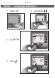
page 8 of 74 Reset / Language selection 1 switch off 2 press both C V C 3000 3 turn D eutsch E nglish Français Italiano E spañol Türkçe 한국어 中文 C VC 3000 4 press D eutsch English Français Italiano Español Türkçe 한국어 中文 V 2.0 Portuguê Ρyccкий Polski N ederl. 日本語 Suomi V 2.0 P ortuguê Ρ yccкий P olski N ederl.
page 9 of 74 Contents Reset / Language selection.............................................. 8 Safety information!............................................................ 11 Important information!.........................................................................11 General information............................................................................ 13 Intended use......................................................................................
page 10 of 74 Readjustment..................................................................... 51 Calibration in the factory.................................................. 53 Cleaning the pressure transducer................................... 53 Interface parameters......................................................... 55 Setting of the interface...................................................................... 55 Read commands ”CVC 2000”.........................................................
page 11 of 74 Safety information! Important information! + Keep this manual complete and accessible to personnel at all times! + Read this manual carefully before installing or operating the equipment. Observe the instructions contained in this manual. + Do not modify the equipment without authorization. NOTICE This manual is an integral part of the equipment described therein. It describes the safe and proper use of the vacuum controller.
page 12 of 74 ➨ DANGER indicates a hazardous situation which, if not avoided, will result in death or serious injury. + WARNING indicates a hazardous situation which, if not avoided, could result in death or serious injury. NOTICE • CAUTION indicates a hazardous situation which, if not avoided, could result in minor or moderate injury. NOTICE is used to address practices not related to personal injury. Disconnect equipment from AC power. Dispose off electronic equipment according to regulations.
page 13 of 74 General information NOTICE Remove all packing material from the packing box. Remove the product from its packing-box and retain all packaging until the equipment is inspected and tested. Inspect the equipment promptly and carefully. If the equipment is damaged, notify the supplier and the carrier in writing within three days. Retain all packing material for inspection. State the item number of the product together with the order number and the supplier’s invoice number.
page 14 of 74 troller in a cabinet or a housing. Make sure ventilation is adequate to maintain recommended operating temperature. Install an external automatic ventilation system if necessary. If processing hot gases, make sure that the maximum permitted gas temperature at the pressure transducer is not exceeded (see “Technical data”, pg. 21). NOTICE Use the equipment only as intended, that is, for measurement and control of vacuum in vessels designed for that purpose.
page 15 of 74 NOTICE Assemble and lock the suitable power plug (included in shipment) to the power supply prior to use. The controller is equipped with a short-circuit-proof, widerange power supply with an integrated overload protection. Position the controller and its vacuum line in such a way that condensate cannot flow towards the pressure transducer. In case connect inert gas at the venting connection.
page 16 of 74 EN 61010-1 gives in detail the conditions under which the equipment can be operated safely (see also IP degree of protection, “Technical data”, pg. 21). Operating conditions ➨ This device is not approved for operation in potentially explosive atmospheres. Do not operate the device in potentially explosive atmospheres. ➨ Controllers without the ”`” mark on the rating plate are not approved for operation with dangerous or explosive gases or with potentially explosive or inflammable substances.
page 17 of 74 + Prevent any part of the human body from coming into contact with vacuum. ☞ Attention: At pressures above approximately 795 Torr (1060 mbar) the pressure reading becomes incorrect due to saturation of the pressure transducer. The display flashes.
page 18 of 74 Ensure that the controller is completely decontaminated before maintenance commences. Take adequate precautions to protect people from the effects of dangerous substances if contamination has occurred. Use appropriate protective clothing, safety goggles and protective gloves. ☞ Vent the vacuum connection before starting maintenance. Isolate the controller from the vacuum system. NOTICE Ensure that maintenance is done only by suitably trained and supervised technicians.
page 19 of 74 ` Important information: Equipment marking (ATEX) VACUUBRAND equipment bearing mark (see rating plate) ` II 3G IIC T3 X Internal Atm. only Tech. File Ref.: VAC-EX01 and VACUUBRAND equipment bearing mark (see rating plate) ` X see manual For equipment labelled with „` X see manual“ the following classification according to Directive 94/9/EC (ATEX) is valid: ` II 3G IIC T3 X, Internal Atm. only, Tech. File Ref.: VAC-EX01.
page 20 of 74 The pumps are marked with ”X” (according to EN 13463-1), i.e., restrictions of the operation conditions: • The equipment is designated for a low degree of mechanical stress and has to be installed in a way so that it cannot be damaged from outside. Pumping units have to be installed so that they are protected against shocks from the outside and against glass splinters in the event of breakage (implosion).
page 21 of 74 Technical data Technical data of controller Controller Pressure transducer Display Pressure units / scale (selectable) CVC 3000 detect ceramic diaphragm (alumina), capacitive, absolute pressure, gas type independent LCD graphic display, illuminated Torr, mbar or hPa Measuring range (absolute) 810 - 0.1 Torr (1080 - 0.1 mbar) Maximum control range (absolute)* 795 - 0.1 Torr (1060 - 0.
page 22 of 74 Controller CVC 3000 detect Interface RS-232 C Weight (without power supply) 2.2lbs. (1.0kg) table top unit:3.3lbs. (1.5kg) Dimensions L x W x H approx. 4.9” x 4.9” x 4.5” (124 mm x 124 mm x 114 mm) table top unit: 7.5” x 6.4” x 6.9” (181 mm x 162 mm x 174 mm) * The actual vacuum control range in your application might be reduced due to ultimate vacuum of the pump, volume of gas present, etc.
page 23 of 74 Technical data of solenoid operated in-line valve Solenoid operated in-line valve VV-B 6C Operating cycles per minute max. 50 Power draw 6W Maximum permissible range of supply voltage 24V DC ±10% Current draw approx. 0.22 A Degree of protection IEC 529 IP 65 Max. permissible differential pressure, pressure gradient in direction of flow-through 1.
page 24 of 74 Use and operation Assembling the country-specific power plug ☞ The wall power supply is delivered with power plugs for Europe, UK, US and Australia. ☞ Press the locking key at the wall power supply to remove and to replace the power plug with your country-specific plug. ☞ Assemble the suitable power plug to the power supply and lock.
page 25 of 74 Attention: Do not assemble or remove plug connections off-axis! Orient the plug correctly before inserting. To connect additional components use VACUU•BUS Y-adapters and extension cables. If an external pressure transducer is connected, it is recognized automatically. Further information on how to use several sensors simultaneously is available upon request. Keys VENT: • A short tap vents momentarily; process continues.
page 26 of 74 CVC 3000 detect (table top unit) solenoid operated in-line valve VV-B 6C vacuum connection to application connection to pump CVC 3000 detect (rear side) jacks for connection of VACUU•BUS components (e.g.
page 27 of 74 Notes on connecting and operating the controller The vacuum controller CVC 3000 detect is fitted with an in-line valve VV-B 6C at its rear. The controller can switch a possibly connected coolant and/or venting valve. The CVC 3000 detect is equipped with an internal capacitive pressure transducer with ceramic diaphragm. It measures the actual pressure independently of the gas type, and with reference to the vacuum, i.e., absolute.
page 28 of 74 Display and symbols Vac control 100 1013.2 mbar Selected function (displayed in the upper left corner): A ”function” is one of the following operation modes of the CVC 3000 detect controller: Pump down / Vac control / detect / Program / VACUULAN / Configuration Other display symbols: 1013.
page 29 of 74 100 Vacuum control to a preset vacuum value (here: 100 mbar/Torr/hPa) / Actual pressure is in the range ”Set vacuum + hysteresis” det.
page 30 of 74 Notes on selecting the function The CVC 3000 detect controller can be adapted to the specific application by choosing the appropriate function depending on the connected components and the requirements of the application. Automatic detection of the components When switching on the controller, the configuration of the connected components is checked automatically. Connected components (e.g.
page 31 of 74 • Coolant valve ”detect” • Provides fully automatic boiling point determination and switches an in-line valve and/or a pump to maintain that pressure in two-point control. • Coolant valve ’’Program’’ • Control in-line valve or pump based on time and pressure preselections. • Coolant valve • Venting valve ”VACUULAN” • Switches a pump (VMS, see ”Accessories”, pg. 63, required) and an in-line valve depending on preselected pressure and time settings.
page 32 of 74 Menu guide Pump down Pump down * MODE 1013.2 mbar * Function Minimum Off Delay Off Duration Off - - - - - - Graphic - - - - - - - - - - - - Back - - - - - - - Pump down Vac control detect Program VACUULAN Configuration Configuration Adjustment 760 Torr RS-232... Sensors... Display... Autostart Off Defaults Cancel - - - - - - - Back - - - - - - - - - - - - - - - Back - - - - - - - * VACUULAN MODE 1013.
page 33 of 74 Vac control Vac control * MODE Set vacuum 75 Torr Hysteresis Auto Maximum Off Delay Off Duration Off - - - - - - Graphic - - - - - - - - - - - - Back - - - - - - - 1013.2 mbar detect * Function Pump down Vac control detect Program VACUULAN Configuration Sensitivity normal Hysteresis Auto Delay Off Duration Off - - - - - - Graphic - - - - - - - - - - - - Back - - - - - - - detect MODE - - - - - - - - Back - - - - - - - 1013.2 mbar * Program MODE 1013.
page 34 of 74 Pump down function ➨ Continuous pumping with pressure and time settings • Operation of a vacuum pump via in-line valve • Operation of a vacuum pump without in-line valve with VMS (Vacuum Management System, see “Accessories”, pg. 63) Preselections ☞ Use the selection knob to select the parameters. All parameters can be altered even while operation control is running.
page 35 of 74 The screen-shot shows the factory-set values. Pump down 00:00:00 Minimum Delay Duration Off Off Off Pump down 10 mbar 00:03:50 - - - - - - Graphic - - - - - - - - - - - - Back - - - - - - - When selecting ”Graphic” the display shows a pressure vs. time curve. The timeline in the diagram adapts automatically to the process time. ☞ Press the selection knob twice to return to the standard display.
page 36 of 74 ☞ Set vacuum: The ”Set vacuum” is the lower set point for two-point vacuum control. The ”Set vacuum” is adjustable in a range of 0-795 Torr (0-1060 mbar). ☞ Hysteresis: The ”Hysteresis” is the control bandwidth of the two-point control. A too small hysteresis will lead to frequent switching of the valve or the pump. A too large hysteresis will lead to imprecise control.
page 37 of 74 The screen-shots show the factory-set values. Vac control 00:00:00 Vac control Set vacuum 75 Torr Hysteresis Auto Maximum Off Delay Off Duration Off - - - - - - Graphic - - - - - - - - - - - - Back - - - - - - - When selecting ”Graphic” the display shows a pressure vs. time curve. The timeline in the diagram adapts automatically to the process time. ☞ Press the selection knob twice to return to the standard display.
page 38 of 74 detect function ➨ Controls a vacuum pump by switching an in-line valve. Automatic determination of the boiling vacuum and automatic switching to the ”Vac Control” function once the boiling vacuum has been determined. The determined boiling vacuum is used in the ”Vac Control” function as ”Set vacuum”. I.e., the controller controls the vacuum to the determined boiling vacuum, see section ”Vac Control function”. + Use the selection knob to select the parameters.
page 39 of 74 ☞ Duration: ”Duration” determines the total process time since control start. The ”Duration” is adjustable between 1-1440 minutes (24 h) or can be set to ”Off”. (”Off” means that no endpoint for pump down is preset.) The screen-shot shows the factory-set values. detect 00:00:00 Sensitivity normal Hysteresis Auto Delay Off Duration Off - - - - - - Graphic - - - - - - - - - - - - Back - - - - - - - detect 430 mbar 00:07:45 When selecting ”Graphic” the display shows a pressure vs.
page 40 of 74 Program function ➨ Permits ten programs to be defined and stored, each with up to ten program steps with preset values for vacuum and time. ➜ ☞ Edit: Use to define the preset values for the process run: Time: Defines either the process runtime for each program step to reach a preset vacuum level or, if programming a ”Step”, the runtime after having achieved the vacuum level. The total process runtime is shown in the base line.
page 41 of 74 ☞ Delay: ”Delay” determines the time the coolant valve remains open after the process has been stopped. Determines also the time the pump (only with VMS module and in-line valve) remains running after the process has been stopped. The ”Delay” is adjustable in a range of 1-300 minutes or can be set to ”Off” (”Off” means that the coolant valve closes immediately - and that a pump with VMS module and in-line valve is switched off immediately - when the process stops.).
page 42 of 74 This program can be transferred to a storage space and edited. Once the program is finished, the clock symbol starts to flash. Confirm the end of the program by pressing START/STOP (clock symbol will disappear). Attention: If ”Autostart” is set to ”On”, the program will start again (time will be reset to 00:00:00) after a power failure or after switching the controller off/on.
page 43 of 74 sure unit) and 20 Torr/mbar/hPa. The determined boiling vacuum is used in the ”Vac Control” function as ”Set vacuum”. In case no boiling vacuum is detected, the controller controls to 20 Torr/mbar/hPa. The following step starts once the cumulative process time reaches the set limit (1 hour/60 minutes), even if the preset pressure (20 Torr/mbar/hPa) has not been reached. Step 4 vents to atmospheric pressure as fast as possible and switches off the control after one minute.
page 44 of 74 VACUULAN function ➨ Optimizes vacuum control for vacuum networks (e.g., VACUUBRAND VACUU•LAN) - pump control only with VMS Preselections ☞ Use the selection knob to select the parameters. ☞ Set vacuum (the lower switch-off value): If the pressure drops below the ”Set vacuum”, a time-meter starts to run. When the pressure exceeds the ”Set vacuum” pressure again, the time meter is reset. If the ”Set vacuum” is not reached within 100 hours, the controller signals an error.
page 45 of 74 This screen-shot shows the factory-set values. VACUULAN 00:00:00 Set vacuum 19 Torr Switch on 150 Torr Delay 15 min - - - - - - Graphic - - - - - - - - - - - - Back - - - - - - - VACUULAN 40 mbar 00:13:00 When selecting ”Graphic” the display shows a pressure vs. time curve. The timeline in the diagram adapts automatically to the process time. ☞ Press the selection knob twice to return to the standard display.
page 46 of 74 Application examples Assembly of a vacuum system ☞ Assemble vacuum connection lines between controller, vacuum pump (diaphragm pump with in-line valve or Vacuum-Management-System) and vacuum application. ☞ Assemble electrical connections. ☞ Connect coolant if necessary. Vacuum for distillation and evaporation (e.g., rotary evaporator) 1. Fully automatic determination the boiling point ☞ Select ”detect” function. ☞ Start process by pressing ”START/STOP” key.
page 47 of 74 has evaporated and the controller is set again to the ”detect” function, further components of the solvent mixture can be evaporated by restarting the ”detect” function. 2. Semi-automatic distillation and evaporation ☞ Select ”Pump down” function. ☞ Start process by pressing ”START/STOP” key. ☞ Observe process. As soon as evaporation starts, press ”MODE” key (switching to ”Vac control”). The vacuum level is kept constant (at the boiling pressure).
page 48 of 74 alternatively: ☞ Select ”Vac control” function to dry at a predetermined vacuum level. ☞ Set ”Set vacuum” to the preferred evaporation vacuum of the solvent. Adapt ”Hysteresis” if necessary. ☞ Set a process time (”Duration”) if necessary. ☞ Start process by pressing ”START/STOP” key. Vacuum for filtration and suction ☞ Select ”Pump down” function. ☞ Set ”Minimum” to a value which provides adequate suction but does not lead to evaporation of the solvent.
page 49 of 74 Configuration In the ”Configuration” menu the device parameters are preselected. After 20 seconds without action the function ”Configuration” and its submenus (except submenu ”Sensors”) are quit automatically without storing any possibly changed parameter. Preselections ☞ Use the selection knob to select the parameters. ☞ Adjustment: Adjustment of the pressure transducer under vacuum and/or at atmospheric pressure, see also section “Readjustment”, pg. 51.
page 50 of 74 ☞ Autostart: If ”Autostart” is set to ”On” the controller restarts a running process automatically after a mains failure. If this is unwanted, set ”Autostart” to ”Off”. Attention: If ”Autostart” is preselected, the process starts immediately after power failure without pressing any further key. It is the user’s responsibility to ensure that no dangerous status of the system due to the automatic startup can occur and to provide appropriate safety measures.
page 51 of 74 Readjustment NOTICE The vacuum gauge was adjusted using factory standards, which are traceable through regular calibration in an accredited laboratory (DAkkS calibration laboratory) to the German national pressure standard. Depending on the process and/or accuracy requirements, check the adjustment and readjust if necessary. For readjustment, the device has to be adjusted both at atmospheric pressure as well as under vacuum but only if the reference pressures are known with certainty.
page 52 of 74 Adjustment under vacuum 0 Torr An adjustment under vacuum is only possible if the pressure is lower than 15 Torr (20 mbar) absolute. ➨ Evacuate the measurement connection of the controller or in case that of a connected optional external gauge head VSK 3000 to a pressure < 0.1 Torr (mbar) (e.g., by applying a good two-stage rotary vane pump). ➨ In ”Configuration” menu, select program ”Adjustment” at the controller. ☞ The reading is automatically adjusted to ”zero”.
page 53 of 74 Calibration in the factory Control of measuring equipment The VACUUBRAND DAkkS calibration laboratory is accredited by the Deutsche Akkreditierungsstelle GmbH (national accreditation body of the Federal Republic of Germany) for the measurable variable pressure in the pressure range from 7.
page 54 of 74 ➨ Drain the solvent and dispose of in accordance with regulations. Repeat cleaning if necessary. ➨ Rinse the measurement chamber several times with alcohol in order to remove all solvent residues. ➨ Allow the pressure transducer to dry. ➨ Readjust the pressure transducer if necessary. Readjustment of the controller CVC 3000 detect See section “Readjustment”, pg. 51.
page 55 of 74 Interface parameters The CVC 3000 controller is equipped with a serial interface (RS 232C, nine-pin Sub-D-plug). ☞ Plug-in or remove the cable (cable RS 232C) from the interface only if the equipment is switched off. ☞ The interface is not electrically isolated from the measuring circuit. ☞ For optimal electromagnetic compatibility assemble an interface filter (cat. no.: 638235). The controller is fully operable via the serial interface.
page 56 of 74 ➨ A maximum of ten commands per second is possible. ➨ Read commands and commands ”REMOTE”, ”CVC”, and ”STORE” can always be sent. The sending of other write commands is only possible, if ”Remote on” is selected. ➨ The commands have to be written in capital letters. ➨ Command and parameter have to be separated by a blank. ➨ The string is terminated with or or . ➨ The response of the controller is always terminated with .
page 57 of 74 Command IN_ERR Operation error code Response 1XXX X1XX XX1X XXX1 0XXX 1XXX X0XX X1XX XX00 XX01 XX02 IN_STAT status of process control XX03 XX10 XX11 XX20 XX21 XX22 XX23 XX30 XX31 Description fault at pump electronics overpressure maloperation mode pressure transducer last command to interface incorrect coolant valve closed coolant valve open venting valve closed venting valve open VACUU•LAN: inactive VACUU•LAN: pumping down, current pressure > selected pressure VACUU•LAN: pumping down,
page 58 of 74 Command Operation OUT_SP_3 vacuum for switch on (VACUU•LAN) XXXX unit (mbar/Torr/hPa) according to preselection; see respective function for parameter range OUT_SP_4 delay XX:XX hh:mm (hours:minutes) XXXX unit (mbar/Torr/hPa) according to preselection; see respective function for parameter range XX:XX hh:mm (hours:minutes) OUT_SP_5 OUT_SP_6 START STOP REMOTE OUT_VENT vacuum for automatic switching off time for automatic switching off (VACUU•LAN) Parameter Description start
page 59 of 74 Read commands ”CVC 3000” Command Operation Response IN_PV_1 current pressure XXXX.X mbar/Torr/hPa IN_PV_2 current speed XXX% IN_PV_3 time XX:XX h:m IN_PV_X pressure XXXX.X XXXX.X ...
page 60 of 74 Command IN_STAT Operation status process control Response 0XXXXX 1XXXXX X0XXXX X1XXXX XX0XXX XX1XXX XXX0XX XXX1XX XXXX0X XXXX1X XXXX2X XXXX3X XXXX4X XXXX5X XXXXX0 XXXXX1 XXXXX2 XXXXX3 0XXXXXXXX 1XXXXXXXX X0XXXXXXX X1XXXXXXX XX0XXXXXX XX1XXXXXX XXX0XXXXX XXX1XXXXX XXXX0XXXX XXXX1XXXX XXXXX0XXX XXXXX1XXX XXXXXX0XX XXXXXX1XX XXXXXXX0X XXXXXXX1X XXXXXXXX0 XXXXXXXX1 IN_ERR fault status IN_SP_1 set vacuum XXXX mbar/Torr/hPa IN_SP_2 maximum speed XXX% IN_SP_3 switching pressure XXXX m
page 61 of 74 Command Operation Response Description IN_SP_5 switch off pressure XXXX mbar/Torr/hPa IN_SP_6 runtime XX:XX h:m IN_SP_P1y time XX:XX:XX h:m:s IN_SP_P2y pressure XXXX mbar/Torr/hPa ”Maximum” for ”Vac control”, ”Minimum” for ”Pump down”) unit according to preselections process runtime (hours:minutes) time in program step y (0......9) (hours:minutes:seconds) 0 pressure in program step y (0......9) unit according to preselections no venting valve in program step y (0......
page 62 of 74 Command Operation Parameter OUT_SP_V set vacuum with venting XXXX OUT_SP_2 speed XXX OUT_SP_3 start-up pressure XXXX unit according to preselection; see respective function for parameter range OUT_SP_4 delay XX:XX hh:mm (hours:minutes) OUT_SP_5 switch-off pressure XXXX unit according to preselection; see respective function for parameter range OUT_SP_6 switch-off time XX:XX hh:mm (hours:minutes) OUT_SP_PL open program X program 0......
page 63 of 74 * If remote operation is selected or deselected, the user has to ensure that no dangerous status of the system can occur due to the change of the mode of operation, and must also take appropriate safety precautions, especially if selecting remote operation interferes with a locally operated active process. ** With command ”ECHO 1” a return value can be activated at write commands. A return value is only given if the command is performed correctly.
page 64 of 74 Conversion of VACUUBRAND valves with DIN plug to VACUUBRAND valves with VACUU•BUS plug: VACUUBRAND-valve with DIN plug Conversion kit valve cable with VACUU•BUS plug In-line valve VV 6, 24V= (674090) In-line valve VV 6C, 24V= (674091) in-line valve VV 15, 24 V= (674110) in-line valve VV 15C; 24V= (674115) 612556 (conversion to in-line valve) 612566 (conversion to venting valve) Coolant valve VKW, 24 V= (676013) 612567 Venting valve VBM, 24 V= (666817) 612554
page 65 of 74 Troubleshooting Fault Possible cause Remedy ❑ No display. ➨ Power supply not ✔ Plug in power supply. plugged in (wall plug)? ➨ CVC 3000 detect controller switched off? ✔ Switch on controller. ➨ VACUU • BUS cable of power supply not plugged in at controller? ✔ Plug in VACUU • BUS cable at controller. ➨ Other than above men- ✔ Contact local distributor. tioned causes? ❑ Display disappears. ➨ Too much load (e.g., valves) connected? ✔ Check current draw of the connected devices.
page 66 of 74 Fault Possible cause Remedy ❑ Warning triangle and black valve symbol are flashing, two blips*. ➨ External venting valve removed or defective? ✔ Connect valve or replace with a new one or reconfigure without valve. ❑ Warning triangle and valve symbol are flashing, three blips*. ➨ In-line valve and NT VARIO / VARIO-B pump connected? ✔ Disconnect VARIO / VARIO-B pump; switch controller off/on to reconfigure.
page 67 of 74 Fault Possible cause Remedy ❑ ”Vac control” func- ➨ Preset maximum pres- ✔ Confirm by pressing tion: Control stops, sure exceeded? START/STOP key. ”arrow up” is flashChange maximum presing. sure value if necessary. ❑ ”Pump down” func- ➨ Pressure below preset ✔ Confirm by pressing tion: Control stops, minimum pressure? START/STOP key. ”arrow down” is Change minimum presflashing. sure value if necessary. ❑ No function is displayed. No menu available.
page 68 of 74 Notes on return to the factory Repair - return - DKD calibration NOTICE Safety and health of our staff, laws and regulations regarding the handling of dangerous goods, occupational health and safety regulations and regulations regarding safe disposal of waste require that for all pumps and other products, the “Health and safety clearance form”, pg. 71, must be sent to our office fully completed and signed before any equipment is shipped to the authorized service center.
page 69 of 74 We submit repair quotations only on request and always at the customer’s expense. If an order is placed, the costs incurred for problem diagnosis are offset from the costs for repair or from the purchase price, if the customer prefers to buy a new product instead of repairing the defective one. - If you do not wish a repair on the basis of our quotation, the equipment may be returned to you disassembled and at your expense.
page 70 of 74 Scrapping and waste disposal: Dispose of the equipment and any components removed from it safely in accordance with all local and national safety and environmental requirements. Particular care must be taken with components and waste oil which have been contaminated with dangerous substances from your processes. Do not incinerate fluoroelastomer seals and O-rings. - You may authorize us to dispose of the equipment at your expense.
page 71 of 74 Health and safety clearance form Devices will not be accepted for any handling before we have received this declaration. Please read and comply with ”Notes on return to the factory”. Oil filled pumps: Drain oil prior to shipping absolutely! 1. Device (Model): ................................................................... 2. Serial no.: ......................................... 3. Reason for return / malfunction: ............................................................................
page 72 of 74 EG-Konformitätserklärung für Maschinen EC Declaration of Conformity of the Machinery Déclaration CE de conformité des machines Hersteller / Manufacturer / Fabricant: VACUUBRAND GMBH + CO KG · Alfred-Zippe-Str. 4 · 97877 Wertheim · Germany Hiermit erklärt der Hersteller, dass das Gerät konform ist mit den Bestimmungen der Richtlinien 2006/95/EG und 2004/108/EG. Hereby the manufacturer declares that the device is in conformity with the directives 2006/95/EC and 2004/108/EC.
page 73 of 74 This certificate is only valid for pumps with the respective mark (Licensed Test mark) on the pump rating plate.
page 74 of 74 Disclaimer: Our technical literature is only intended to inform our customer. The validity for specific applications of general empirical values and results obtained under test conditions depends on a number of factors beyond our control. It is therefore strictly the users’ responsibility to very carefully check the validity of application to their specific requirements. No claims arising from the information provided in this literature will, consequently, be entertained. Alfred-Zippe-Str.