IP-MR18 Door Station User Manual RF CARD 1 2 3 4 5 6 7 8 9 * 0 # Please read this manual carefully before using the product you purchase, and keep it well for future use.We reserve the right to modify the specification in this manual at any time without notice.
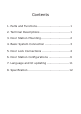
Contents 1. Parts and Functions...................................1 2. Terminal Descriptions................................1 3. Door Station Mounting...............................2 4. Basic System Connection...........................3 5. Door Lock Connections..............................4 6. Door Station Configurations.......................6 7. Language and UI updating........................11 8. Specification...........................................
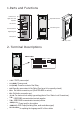
1.Parts and Functions Camera Lens Night View LED Adjustable Camera 350 mm Speaker LCD Screen ID Card Window Digital Keypad Connectiong Port RF CARD 3 2 1 1 2 3 4 5 6 7 8 9 * 0 # Microphone 128 mm With rainy cover 2. Terminal Descriptions SD Card Slot • • • • • • • • • • • • +12V EB+ EBN.O LK+ LK3 2 1 J/KMB RS-485 JWP T/R -T/R+ PP+ CN-LK 3 2 1 JWB(OUT) JP-LK +12V: 12VDC power output. LK-(GND): Power ground. LK+(COM): Common contact of the Relay . NO.
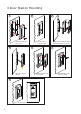
3.Door Station Mounting 1 2 3 Camera angle mm 395mm 147 42m m The view for rainy cover after mounted Drill a hole and attach the rainy cover to it 4 5 Attach screws to fix the metal box 7 The last view for all mounting -2- Adjust the camera angle and attach the metal to the panel and wire correctly.
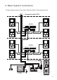
4. Basic System Connection The basic system consists of: Door station, Distributor, Monitor, Power supply and lock. Connect to next C5-F4 C5-F4 C5-F4 CN-LK PS5 RF CARD 12 V DC lock +12V - EB+ EBN.
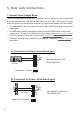
5. Door Lock Connections 1. Internal Power Supply Mode Use the internal power to supply for the electronic lock, so that the lock can be connected to the door station directly. Note that the door station can only output 12Vdc power, Any highpower lock should use external power connection or it might cause damage to the door station.
2. External Power Supply Mode When the electronic lock is over 12 Vdc, additional power supply for the lock is needed. • The power supply for the lock must be less than 48Vdc 1.5A. • The Jumper must be removed when using external power supply. The default setting is Power-on-to-Unlock type(Normally open mode), if use Power-off-to-Unlock type, change the Unlock Relay mode to Normally closed mode . • If different unlocking time is needed to be configured, change the Unlock Timing on door station. C.
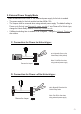
6. Door Station Configurations About Debug State: The Debug State is your starting point for using all the applications. To open the debug state,please refer to the following steps: >> Debug State << RF CARD 1 4 2 3 5 6 7 8 9 * 0 # 0-# Redial 1-# To o l s 2-# Exits [9008] Please Input Password When Door Station is in standby, press '#' key Input '9008', then input the Admin Code.(66666666 by default) Debug State menu is launched Press "2#" key to exit out the debug state.
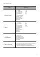
Table 1:Menu overview Item Submenu 1. Installer Setup 1. ID Code [0] 2. Unlock Timing [05] 3. Unlock Output [0] 4. Card Memory [0] 5. Doorplate Mode 6. Audio Options ... 7. Parameters ... 8. Installer Code ... 9. Default ... 2. Setup 1. Language [1] 2. Tone Select [03] 3. Tone Volume [08] 4. Unlock Code [1111] 5. Display Mode 6. Clock ... 7. Setup Code ..
Basic Tools Detail: Table 2(Installer Setup): Item ID Code Unlock Timing Unlock Output Card Memory -8 - Factory set Description 1.When there is only one door station and no C5-IPC, set to 0. And set the type of distributor used with it. When C5-IPC is connected, must not be set to 0. 2. When C5-MDS is connected, be set to from 1~8 according to which port it is connected on the C5-MDS 3. When used as common door station, set to 9 To set the time that how long the door keeps open when door is released.
Table 2.
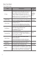
Table 3(Setup): Item Language Tone Select Tone Volume Unlock Code Display Mode Clock ... Setup Code -10- Description To change language.the code format is 4 digits.Please refer to section 7(Language and UI updateing) for more detail informations. Select the chime of Door Station in calling wait state, 12 chord tunes are available, key in 01 to 12 to select. Adjust the tone volume for dooor station in calling.
Table 4(Card Manage): Item Factory set Description Add Card ... To add user cards, input the room code and then swipe the card to be added - Delete By Card To swipe the card to be deleted - Delete By M.code Cards Information Format To delete the card by room code. Input the room code, and all the cards attached to it will be deleted To show the amount of cards added To count how many times cards are swiped To delete all the cards and count information - 7.
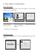
Step 1: Insert the SD card which is contained config files into the SD card slot where is at the back of the door station.Refer to the right diagram. Step 2:If door station runs as Debug State, you can press “1#” to activate Tools Menu, select “2” to enter setup page,then select 1 item.If it runs as Normal State, follow these steps: Setup [ 8002 ] 2 3 4 5 6 7 8 9 * 0 # 1. Language [----] 4. Unlock Code[1111] 5. Display Mode RF CARD 1 1. Language [1] 2 . To n e S e l e c t [ 0 3 ] 3 .
C5-ENG-MR18-V1 2011S1228