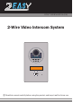
DT597 USER MANUAL(EN) 2-Wire Video Intercom System Read this manual carefully before using the product, and keep it well for future use.
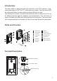
Introduction The door station is designed with high resolution color CCD camera, it provides wide angle of 1050 for DT 2-wire intercom system. The high white LED for night view makes the door station working efficiently at night. The front panel is made of medical stainless steel with a thickness of 2.5 mm for better protection against vandalism and cauterization. The call button is made of durable zinc alloy with white backlight for illumination.
Lock Control Jumper: To select the lock type. Door Station Code DIP: Total 4 door stations can be supported. T/R+,T/R-: USB-RS485 communication terminal. Main Connect Port: To connect the bus line and the electronic locks. BUS: Connect to the bus line, non-polarity. PL: External lock power input, connect to the power positive(power +). S1+, S2+: Lock power(+) output, to connect 2 locks. S-: Lock power(-) output. Door Station Mounting 1 2 3 4 CLOSE 90° OPEN Steps: 1.
Placing Name Label 1 2 3 n Ope se Clo 90° Steps: 1. Use the special spanner to move 900 to loosen the screw. 2. Open the front panel. 3.
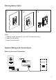
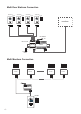
Multi Door Stations Connection 4# Camera 3# Camera ID=11 2# Camera 1# Camera ID=10 ID=01 ID=00 ON ON ON ON 12 1 2 1 2 1 2 monitors L1 L2 PL S1+ S2+ S- L1 L2 PL S1+ S2+ S- L1 L2 PL S1+ S2+ S- L1 L2 PL S1+ S2+ S- 85~260VAC AC~ DIP=on,off,off A B C D PC6 DBC-4S OFF ON Impedance switch Multi Monitors Connection ON ON ON ON 1 2 3 4 5 6 1 2 3 4 5 6 1 2 3 4 5 6 1 2 3 4 5 6 Code=0, DIP-6=off Code=1, DIP-6=off Code=14, DIP-6=off Code=15, DIP-6=on monitor monitor monitor monitor
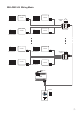
With DBC-4S Wiring Mode ON monitor monitor 1 2 3 4 5 6 Impedance switch Code=14, DIP-6=on A B C D Code=15, DIP-6=on ON ON monitor Code=12, DIP-6=on Code=13, DIP-6=on ON 1 2 3 4 5 6 DIP=on,off,off monitor 1 2 3 4 5 6 ON monitor Code=2, DIP-6=on Impedance switch A B C D Code=3, DIP-6=on monitor 1 2 3 4 5 6 1 2 3 4 5 6 Code=1, DIP-6=on DIP=on,off,off ON ON monitor OFF ON DBC-4S 1 2 3 4 5 6 OFF ON DBC-4S ON 1 2 3 4 5 6 monitor 1 2 3 4 5 6 Code=0, DIP-6=on AC~ PC6 ID=00
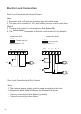
Electric Lock Connection Door Lock Controlled with Internal Power Note: 1. Electronic lock of Power-on-to-unlock type should be used. 2. The door lock is limited to 12V, and holding current must be less than 250mA. 3. The door lock control is not timed from Exit Button(EB). 4. The Unlock Mode Parameter of Monitor must be set to 0 (by default).
connect one lock connect two locks Take off the Jumper BUS PL S1+ S2+ Take off the Jumper S- BUS POWER SUPPLY PL S1+ S2+ S- POWER SUPPLY LOCK LOCK LOCK 5.2.3 Unlock parameter setting(set on monitor) Manual Monitor Memory Playback Monitor Album Intercom Multimedia Close User Setup 09/30/2010 Thu.16:41 1.Touch menu page. item on main H/W : S/W: Local addr: Unlock timing: Video standard: UI-CODE: MCM-VER.: Updated: --- a1.3 V17.11.418.00 ----------- 2.
DIP Switches Setting The DIP switch is designed to set the code for door station and monitor, there are two states for each DIP switch, please refer to the sketch map. ON(1) ON = OFF(0) ON = Door station DIP setting Total 2 bits can be configured, bit-1 and bit-2 are used to assign ID code for door station.The switches can be modified either before or after installation. Bit state ON Descriptions Default setting, ID = 0(00), set to the first Door Station.
Bit state ON 1 2 3 4 5 6 User code code=0 ON 1 2 3 4 5 6 ON 1 2 3 4 5 6 ON 1 2 3 4 5 6 ON ON 1 2 3 4 5 6 User code code=6 ON ON 1 2 3 4 5 6 Bit state code=1 code=2 code=3 code=4 1 2 3 4 5 6 ON 1 2 3 4 5 6 ON 1 2 3 4 5 6 ON 1 2 3 4 5 6 Bit state ON 1 2 3 4 5 6 User code code=11 ON code=7 code=8 code=9 code=10 1 2 3 4 5 6 ON 1 2 3 4 5 6 ON 1 2 3 4 5 6 ON 1 2 3 4 5 6 code=12 code=13 code=14 code=15 code=5 1 2 3 4 5 6 Specification Power Supply : DC 24V (supplied by PC6); Power Co
Cables Requirements The maximum distance of the wiring is limited in the DT system. Using different cables may also affect the maximum distance which the system can reach. The farest monitor monitor with two or four monitors monitor monitor DBC-4S B C AC~ PC6 When Monitor quantity < 20 Cable Usage A B C Twisted cable 2x0.75 mm2 60 60 30 Twisted cable 2x1 mm2 80 80 40 When Monitor quantity > 20 Cable Usage A B C Twisted cable 2x1 mm2 70 30 20 Twisted cable 2x1.
The design and specifications can be changed without notice to the user. Right to interpret and copyright of this manual are preserved.