2 -Wire Intercom System DT596(F)KP User Manual 1 2 3 1 2 3 4 5 6 4 5 6 7 8 9 7 8 9 * 0 # * 0 # DT596/KP DT596F/KP DT-ENG-596(F)KP-V2 110S714
Contents 1.Parts and Functions............................................................................................. 1 2.Terminal Descriptions........................................................................................... 1 3.Door Station Mounting.......................................................................................... 2 4.System Wiring and Connections.......................................................................... 4 5.DIP Switches Setting.......................
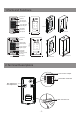
1.
•• •• •• •• Lock Control Jumper: To select the lock type: see section 5 Doorstation Code DIP: Total 4 door stations can be supported,see section 6 MIC: Adjust the volume of Microphone SPK: Adjust the volume of Speaker •• •• •• •• •• Main Connect Port: To connect the bus line and the electronic locks. BUS: Connect to the bus line, no polarity. PL: External lock power input, connect to the power positive(power +). S1+, S2+: Lock power(+) output, to connect 2 locks.
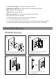
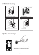
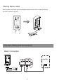
DT596F/KP Mounting 1 2 adjust camera angle 0mm 174mm 9 52m m PS Drill a hole in the wall to match the size of the mounting box and attach to the wall. Connect the cable correctly and adjust right angle for camera 3 4 Attach the panel to the mounting box and use screws supplied to fix the panel Place name label Adjusting Camera Angle use a screwdriver to loosen the screw and then adjust the angle of the camera ,then fix the screw.
Placing Name Label Move the plastic cover away to open the transparent name label cover, insert a name paper, then put the plastic cover back to the panel. 1 2 3 4 5 6 7 8 9 * 0 # 4.
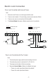
Electric Lock Connection Door Lock Controlled with Internal Power Note: 1. Electronic lock of Power-on-to-unlock type should be used. 2. The door lock is limited to 12V, and holding current must be less than 250mA. 3. The door lock control is not timed from Exit Button(EB). 4. The Unlock Mode Parameter of Monitor must be set to 0 (by default).
connect one lock connect two locks Take off the Jumper BUS PL S1 + S2 + Take off the Jumper S- BUS POWER SUPPLY PL S1 + S2 + S- POWER SUPPLY LOCK LOCK LOCK Unlock parameter setting(set in monitor) Manual Monitor Memory Playback Monitor Album ? About 1.Touch menu page. Intercom H/W : S/W: Local addr: Unlock timing: Video standard: UI-CODE: MCM-VER.: Updated: Multimedia Close User Setup 09/30/2010 Thu.16:41 item on main --- a1.3 V17.11.418.00 ----------- 2.
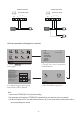
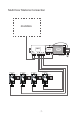
Multi Door Stations Connection monitors DPS DBC4 BUS PS5 A B C D 85~260VAC 4# Camera 3# Camera ID=11 L1 L2 PL S1+ S2+ S- 2# Camera ID=01 1# Camera ID=00 ID=10 ON ON ON ON 1 234 1 234 1 234 1 234 L1 L2 PL S1+ S2+ S- L1 L2 PL S1+ S2+ S- L1 L2 PL S1+ S2+ S- -7-
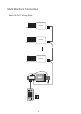
Multi Monitors Connection Basic IN-OUT Wiring Mode ON monitor 1 2 3 4 56 Code=15, DIP-6=on ON monitor 1 2 3 4 5 6 Code=14, DIP-6=off ON monitor 1 2 3 4 5 6 Code=0, DIP-6=off PS5 DPS 85~260AC 1 2 3 4 5 6 7 8 9 * 0 # ID=00 ON 1 234 -8-
With DBC-4 Wiring Mode ON ON 1 2 3 4 5 6 monitor monitor 1 2 3 4 5 6 HI OUT IN Code=14, DIP-6=on Code=15, DIP-6=on A B C D DBC-4 ON ON 1 2 3 4 5 6 monitor Code=13, DIP-6=on ON ON 1 2 3 4 5 6 monitor 1 2 3 4 5 6 Code=12, DIP-6=on monitor HI monitor 1 2 3 4 5 6 OUT IN Code=2, DIP-6=on Code=3, DIP-6=on A B C D 1 2 3 4 5 6 Code=1, DIP-6=on monitor monitor 1 2 3 4 5 6 Code=0, DIP-6=on DPS PS5 85~260AC -9- 1 2 3 4 5 6 7 8 9 * 0 # ID=00 ON 1 2 DBC-4 ON ON
Extending Connections with DCU unit ON ON CALL UNLOCK CALL UNLOCK TALK/MON TALK/MON IN-USE IN-USE 1 2 3 4 5 6 HI 1 2 3 4 5 6 Code=3, DIP-6=on OUT IN Code=2, DIP-6=on ON CALL UNLOCK CALL UNLOCK TALK/MON TALK/MON IN-USE IN-USE 1 2 3 4 5 6 1 2 3 4 5 6 Code=1, DIP-6=on Code=0, DIP-6=on AC DCU Code =3(11) ON ON 123456 DBC-4 BUS 1234 DPS DCU PS5 A B C D 85~260VAC Camera 1 Camera 2 ID=00 1 2 3 1 2 3 1 2 3 4 5 6 4 5 6 4 5 6 7 8 9 7 8 9 7 8 9 * 0 #
5.DIP Switches Setting ON(1) ON OFF(0) ON = = DIP Switches Settings of Door Station Total 4 bits on the DIP switches can be configured.The switches can be modified either before or after installation. Setting Item Bit state ON Descriptions Default setting, ID = 0(00), set to the first Door Station. 1 2 34 ON Bit1 and Bit2 (it is used to set the ID code for door station) ID = 1(10), set to the second Door Station. 1 2 34 ON ID = 2(01), set to the third Door Station.
Bit-1 to Bit-5 are used to User Code setting.The DT596 responds to 0~15 .
Order Setting items Setting range Default value Setting code 1 Reset all settings 1234 - 00 2 Setting the master code 1234 01 3 Setting the key illumination time 1 ~ 12 digits Valid keys:0 ~ 9 10 to 99 seconds/ continually lit 10 seconds 02 4 Setting the unlock time 01 to 99 seconds 1 seconds 03 5 Setting the unlock mode 0:opened/1:closed opened 04 6 Operation tone settings 0:on/1:off on 05 7 Reset code settings 1234 - 06 8 &# function settings 0:Normal/1:Reverse No
1 2 3 4 5 6 7 8 9 * 0 # red blue Each operation is indicated by the lighting up of the LED indicators on the right section of the unit, and by the sounding of the buzzer. (red) ON Input the master code. (Default: [ (blue) OFF ] +[#] ) 1.Reset all settings Beep+, Beep 2.Setting the master code (Default 1234) 3.Setting the key illumination time (Default 10s) 4.Setting the unlock time (Default 1s) Input the setting code. Input the setting code. Input the setting code.
* (red) ON Input the master code. (Default: [ (blue) OFF ] +[#]) 5.Setting the unlock mode (Default 0(opened)) Beep+, Beep 6.Setting operation tone (Default ON) 7.Reset code setting * 8. &# function setting (Default Normal) Input the setting code. Input the setting code. Input the setting code. Input the setting code. 04+# 05+# 06+# 07+# (red) ON (blue) ON (red) ON (blue) ON Beep+, Beep 0/1 Inputting of code (ex.
(red) ON Input the master code. (Default: [ ] +[#]) 9. Call tone setting (Default enable) Beep+, Beep 10.Interference resistant grade setting (Default 2) Input the setting code. Input the setting code. 08+# 09+# (red) ON (blue) OFF (blue) ON (red) ON (blue) ON Beep+, Beep Beep+, Beep 0/1 Inputting of code (ex.: 1) range:0(enable)/1:(disable) 1+# (red) ON 3+# (red) ON (blue) OFF Beep+ - When the “ Inputting of code (ex.
(red) ON Input the master code. (Default: [ (blue) OFF ]+[#] ) 12.Setting the code forTemporary1 Beep+, Beep 13.Setting the code forTemporary2 14.Setting the code for user group1 15.Setting the code for user group2 20~59 Input the setting code. Input the setting code. 18+# 19+# (red) ON (blue) ON (red) ON (blue) ON Beep+, Beep Inputting of code (ex.: 1006) 1~12 digits (blue) OFF - When the “ (blue) OFF 60+# (blue) ON (red) ON Inputting of code (ex.
7.Unlock Operations Unlocking of user code When the registered user code has been input using the keypad (1~12 digits), the LED indicator (group 1: red, group 2: blue) lights up, the buzzer sounds,and the electric door strike is unlocked.
8.Power Supply Instructions Name Discription Usage PS5-24V Power supply,85~260Vac input,24Vdc/3A output,10 DIN modules Connect with multi doorstations or multi monitors(up to 2 or above) PS4-24V Power supply,85~260Vac input,24Vdc/1A Connect with one doorstation and one output,for basic kit only,4 DIN modules monitor(DT16 can be connected two) 9. Precaustions •• Please clean the unit with soft cotton cloth, don't use the organic impregnant or chemical clean agent.
11.Cables Requirements The maximum distance of the wiring is limited in the DT system. Using different cables may also affect the maximum distance which the system can reach. The farest monitor monitor with two or four monitors monitor monitor DBC/DBC-4 B C When Monitor quantity < 20 DPS Cable Usage A B C Twisted cable 2x0.75 mm2 60 60 30 Twisted cable 2x1 mm2 80 80 40 A When Monitor quantity > 20 Cable Usage A B C Twisted cable 2x1 mm2 70 30 20 Twisted cable 2x1.
Note:
The design and specifications can be modified without notice to the user. Right to interpret and copyright of this manual are reserved.