
Manual


-9-
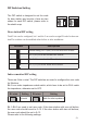
DIP Switches Setting
The DIP switch is designed to set the code
for door station and monitor, there are two
states for each DIP switch, please refer to
the sketch map.
ON(1)
=
OFF(0)
=
ON
ON
Total 2 bits can be congured, bit-1 and bit-2 are used to assign ID code for door sta-
tion.The switches can be modied either before or after installation.
There are 6 bits in total. The DIP switches are used to congure the user code
for Monitors.
Bit-6 is an video impedance match switch, which have to be set to ON if match
the impedance, otherwise set to OFF.
Bit-1~Bit-5 are used to set user code. If the door station with one call button,
the user code should be set to 0~15. If the door station with two call buttons,
the user code should be set to 0~31.
Please refer to the following settings:
Door station DIP setting
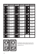
Indoor monitor DIP setting
Bit state Descriptions
Default setting, ID = 0(00), set to the rst Door Station.
ID = 1(10), set to the second Door Station.
ID = 2(01), set to the third Door Station.
ID = 3(11), set to the fourth Door Station.
1
2
ON
1 2
ON
1 2
ON
1 2
ON
Bit state Setting Bit state Setting
Not match Match the video impedance
1 2 3 4 5 6
ON
1 2 3 4 5 6
ON