DT594 USER MANUAL(EN) 2-Wire Video Intercom System Read this manual carefully before using the product, and keep it well for future use.
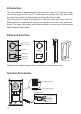
Introduction The door station is designed with high resolution color CCD camera, it provides wide angle of 1050 for DT 2-wire intercom system. The high white LED for night view makes the door station working efficiently at night. The front panel is made of plexiglass or stainless steel with rainy cover for better protection against water. One or two touch sensor call button can be selected. The large name label with white backlight is covered by a fully secured and flameproof glass plate.
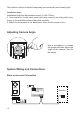
Lock Control Jumper: To select the lock type. Door Station Code DIP: Total 4 door stations can be supported. T/R+,T/R-: USB-RS485 communication terminal. Main Connect Port: To connect the bus line and the electronic locks. BUS(Blue&Green): Connect to the bus line, non-polarity. PL(White): External lock power input, connect to the power positive(power +). S1+(Yellow): The first lock power(+) output. S2+(Red): The second lock power(+) output. S-(Black): Lock power(-) output.
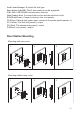
The location of the unit should keep away from snow,rain,and intensity light. Installation Steps: Installation height for door station usually is 145~160cm. 1. Use screws to fix the back panel and rainy cover(if mounting with rainy cover) to the wall after connect the cable correctly. 2. Attach the front panel to the back panel, then use the screw to fix it. Use a screwdriver to loosen the screw and then adjust the angle of the camera ,then fix the screw.
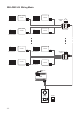
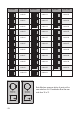
Multi Door Stations Connection 4# Camera 3# Camera ID=11 2# Camera 1# Camera ID=10 ID=01 ID=00 ON ON ON ON 12 1 2 1 2 1 2 monitors Bus PL S1+ S2+ S- Bus PL S1+ S2+ S- Bus PL S1+ S2+ S- Bus PL S1+ S2+ S- 85~260VAC AC~ DIP=on,off,off A B C D PC6 DBC-4S OFF ON Impedance switch Multi Monitors Connection ON ON ON ON 1 2 3 4 5 6 1 2 3 4 5 6 1 2 3 4 5 6 1 2 3 4 5 6 Code=0, DIP-6=off Code=1, DIP-6=off Code=14, DIP-6=off Code=15, DIP-6=on monitor monitor monitor monitor AC~ P
With DBC-4S Wiring Mode ON monitor monitor 1 2 3 4 5 6 Impedance switch Code=14, DIP-6=on A B C D Code=15, DIP-6=on ON ON monitor Code=12, DIP-6=on Code=13, DIP-6=on ON 1 2 3 4 5 6 DIP=on,off,off monitor 1 2 3 4 5 6 ON monitor Code=2, DIP-6=on Impedance switch A B C D Code=3, DIP-6=on monitor 1 2 3 4 5 6 1 2 3 4 5 6 Code=1, DIP-6=on DIP=on,off,off ON ON monitor monitor 1 2 3 4 5 6 Code=0, DIP-6=on AC~ PC6 ID=00 ON 1 2 -6- OFF ON DBC-4S 1 2 3 4 5 6 OFF ON DBC-4S ON
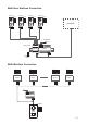
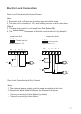
Electric Lock Connection Door Lock Controlled with Internal Power Note: 1. Electronic lock of Power-on-to-unlock type should be used. 2. The door lock is limited to 12V, and holding current must be less than 250mA. 3. The door lock control is not timed from Exit Button(EB). 4. The Unlock Mode Parameter of Monitor must be set to 0 (by default).
connect one lock connect two locks Take off the Jumper BUS PL S1+ S2+ Take off the Jumper S- BUS POWER SUPPLY PL S1+ S2+ S- POWER SUPPLY LOCK LOCK LOCK 5.2.3 Unlock parameter setting(set on monitor) Manual Monitor Memory Playback Monitor Album Intercom Multimedia Close User Setup 09/30/2010 Thu.16:41 1.Touch menu page. item on main H/W : S/W: Local addr: Unlock timing: Video standard: UI-CODE: MCM-VER.: Updated: --- a1.3 V17.11.418.00 ----------- 2.
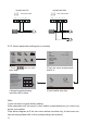
DIP Switches Setting The DIP switch is designed to set the code for door station and monitor, there are two states for each DIP switch, please refer to the sketch map. ON(1) ON = OFF(0) ON = Door station DIP setting Total 2 bits can be configured, bit-1 and bit-2 are used to assign ID code for door station.The switches can be modified either before or after installation. Bit state ON Descriptions Default setting, ID = 0(00), set to the first Door Station.
Bit state ON 1 2 3 4 5 6 User code Bit state ON code=0 1 2 3 4 5 6 User code code=11 ON ON 1 2 3 4 5 6 ON 1 2 3 4 5 6 ON 1 2 3 4 5 6 ON 1 2 3 4 5 6 ON 1 2 3 4 5 6 code=1 ON 1 2 3 4 5 6 ON code=3 1 2 3 4 5 6 ON code=4 1 2 3 4 5 6 ON code=5 1 2 3 4 5 6 ON code=12 code=13 code=14 code=15 code=16 ON 1 2 3 4 5 6 ON 1 2 3 4 5 6 code=6 ON 1 2 3 4 5 6 code=17 code=18 ON ON 1 2 3 4 5 6 ON 1 2 3 4 5 6 code=8 code=22 1 2 3 4 5 6 ON 1 2 3 4 5 6 ON 1 2 3 4 5 6 ON 1 2 3 4 5 6 ON
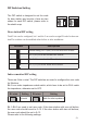
Cables Requirements The maximum distance of the wiring is limited in the DT system. Using different cables may also affect the maximum distance which the system can reach. The farest monitor monitor with two or four monitors monitor monitor DBC-4S B C AC~ PC6 When Monitor quantity < 20 Cable Usage A B C Twisted cable 2x0.75 mm2 60 60 30 Twisted cable 2x1 mm2 80 80 40 A When Monitor quantity > 20 Cable Usage A B C Twisted cable 2x1 mm2 70 30 20 Twisted cable 2x1.
Specification Power Supply : DC 24V (supplied by PC6); Power Consumption: Standby 60mA; Working status 200mA; Camera: 1/4 ACS 4T image sensor with DSP processor Lock Power supply: 12Vdc, 300mA(Internal Power); Working temperature: -10ºC ~ +45ºC Dimension: 188(H)×110(W)×34(D)mm Precautions • Please clean the unit with soft cotton cloth, don't use the organic impregnant or chemical clean agent. If necessary, please use a little pure water or dilute soap water to clean the dust.