
Instruction Manual


1. Parts and Funcons
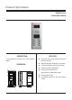
Camera Lens
Infrared LED
Speaker
Microphone
Name plate
Call button
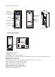
Camera Angle
adjustment
Speaker Vol
adjustment
With rainy cover
CDS Sensor
1 2 3 4 5 6
ON
L1
+12V
T/R -
T/R+
LK - (GND)
CN-LK JP-LK
RS-485
SET
PA
PB
BUS
LK+(COM)
N.O.
EB+
EB -
1
2
3
L2
1 2 3 4 5 6
ON
L1
+12V
T/R -
T/R+
LK - (GND)
CN-LK
RS-485
SET
PA
PB
BUS
LK+(COM)
N.O.
EB+
EB -
1
2
3
L2
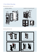
DMR11
Connection Board
• +12V: 12VDC power output.
• LK-(GND): power ground.
• LK+(COM): Common contact of the Relay
• NO.: Normally open contact of the Relay(refer to DT technical guide for Lock connection detail informations).
• EB+: Exit button connection port.
• EB-: Exit buton connection port.
• JP-LK: For electronic lock safety type setting(refer to Door Station Lock Connections).
• T/R-: USB-RS485 communication terminal negative.
• T/R+: USB-RS485 communication terninal positive.
• SET: DIP switches for system congurations.
• PA: program button A(refer to program section).
• PB: program button B.(refer to program section).
• Bus(L1,L2): non-polarised bus line.
Terminal descripon